

 English
  русский
  Español
  عربى
عربى  Português
  Deutsch
  Türk
Türk  Indonesia
")
")
")
Introduction: The HN type slider coupling is a precision-engineered mechanical coupling sy...
Search
Product Category
Hot Products
Contact Us
+86 511 8572 3800
+86 511 8572 3900
+86 15106109009 Keep in touch
Don't hesitate to send a message
+86 511 8572 3900
+86 15106109009 Keep in touch
Brake Drum Gear Coupling Manufacturers
-

-
 SWC-WF type large size universal coupling without expansion flange
Introduction: The SWC-WF Type Large Size Universal Coupling without Expansion Flange is an...
-
 SWC-CH type long expansion welding universal coupling
Introduction: The SWC-CH Type Long Expansion Welding Universal Coupling embodies a sophist...
-
 SWC-WD non-telescopic short universal coupling
Introduction: The SWC-WD Non-Telescopic Short Universal Coupling is a precision-engineered...
-
 QWL Type Ball Cage Universal Coupling
Core Characteristics and Application Analysis of QWL-type Ball Cage Universal CouplingThe ...
-
 SWC-WH type non-expansion welded universal coupling
Introduction: The SWC-WH Type Non-Expansion Welded Universal Coupling represents a versati...
-
 SWC-DH type short expansion welding universal coupling
The SWC-DH Type Short Expansion Welding Universal Coupling is a cutting-edge solution desi...
-
 SWC-BF large size standard expansion flange universal coupling
The SWC-BF Large Size Standard Expansion Flange Universal Coupling represents a pinnacle i...
-
 SWC-BF standard expansion flange type universal coupling
The SWC Standard Telescopic Flange Type Universal Joint Coupling is an advanced engineerin...
-
 SWC-BH standard expansion welded universal coupling
The SWC Standard Telescopic Welded Universal Joint Coupling is a versatile and reliable so...
-
 SWC-WF type flange universal coupling without expansion welding
Introduction: The SWC-WF Type Flange Universal Coupling without Expansion Welding is a pre...
The flexible couplings with non-elastic elements compensate for shaft misalignment through relative movement or clearance between mating components, instead of elastic deformation.
Due to the absence of damping or buffering elements, these couplings offer high torsional stiffness and efficient power transmission, and are typically applied in systems operating under stable rotational speed and constant load conditions.
Our company supplies non-elastic elements flexible couplings in a broad range of sizes and specifications to meet different installation and operating requirements.
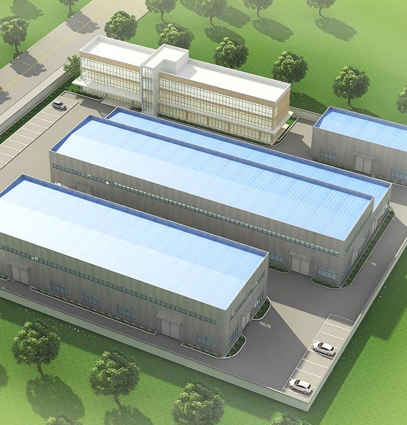
Zhongye Heavy Industry Technology (Zhenjiang) Co., Ltd.
Zhongye Heavy Industry Technology (Zhenjiang) Co., Ltd. is located in a well-known ancient city, Zhenjiang. We are an enterprise integrating R & D, manufacturing, and sales. As China Coupling With Brake Disc Manufacturers and Drum Coupling Factory, our products are widely used in metallurgical equipment, mining equipment, water equipment, lifting equipment, paper equipment, port equipment and other industries.
Our main products are toothed coupling, elastic sleeve column pin coupling, elastic column pin coupling, gear coupling with elastic pin, a universal coupling, tire coupling, jaw coupling, star coupling, diaphragm coupling, drum coupling and grid coupling, the Oldham coupling, flange coupling, clip shell coupling, GL type roller chain coupling and a safety coupling, and so on. Our company also undertakes a variety of non - standard coupling designs and manufacturing.
New workshop covers an area of about 16463.52 m². heavy workshop 5,500 M2, Precision workshop 4,600 m², office building and the gymnasium 2000 M2, Dinning hall 500m², Warehouse 1000 m², Roads, greening, parking areas 3563 M2.
View more
Our main products are toothed coupling, elastic sleeve column pin coupling, elastic column pin coupling, gear coupling with elastic pin, a universal coupling, tire coupling, jaw coupling, star coupling, diaphragm coupling, drum coupling and grid coupling, the Oldham coupling, flange coupling, clip shell coupling, GL type roller chain coupling and a safety coupling, and so on. Our company also undertakes a variety of non - standard coupling designs and manufacturing.
New workshop covers an area of about 16463.52 m². heavy workshop 5,500 M2, Precision workshop 4,600 m², office building and the gymnasium 2000 M2, Dinning hall 500m², Warehouse 1000 m², Roads, greening, parking areas 3563 M2.
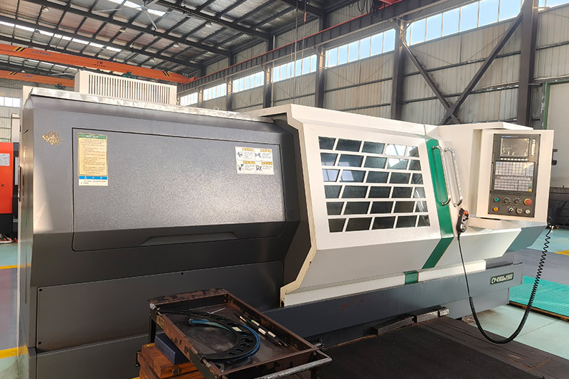
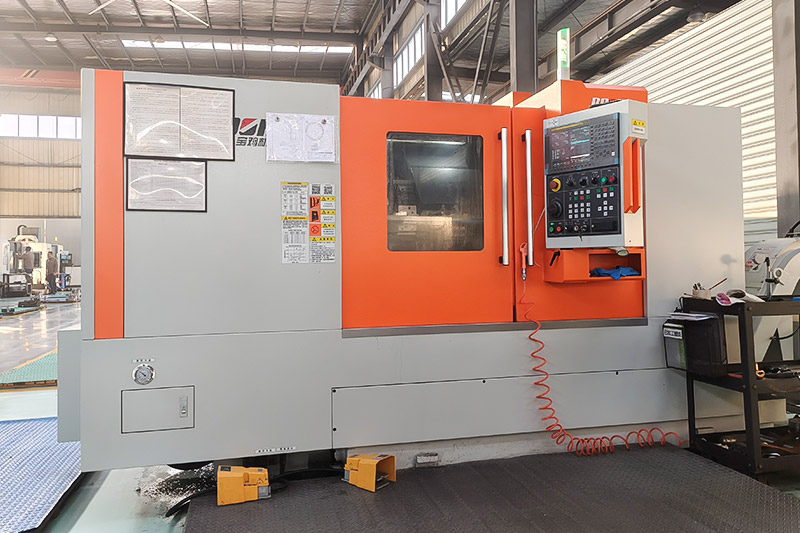
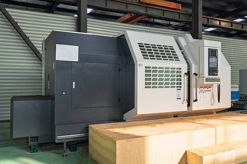
Plant Equipment
FACTORY TOUR
Industry knowledge
Mechanical Performance Advantages of Drum Gear Coupling in Heavy-Duty Applications
One of the most significant mechanical advantages of Drum Gear Coupling lies in its exceptional torque transmission capacity. Heavy-duty equipment such as rolling mills, mining crushers, high-capacity conveyors, hoisting systems, and marine drive mechanisms require components capable of transmitting extremely high torque under continuous load. Drum Gear Coupling is engineered with large module gear teeth and optimized tooth contact surfaces, allowing high torque density within a compact structural envelope. The crowned external teeth design enables uniform load sharing across the full width of the tooth surface. This geometry minimizes localized stress concentration, reducing the likelihood of premature pitting, scuffing, or fatigue cracking. Under heavy operational loads, stress distribution remains balanced along the meshing interface, enhancing structural integrity and operational lifespan. High-grade alloy steels are commonly used in manufacturing to ensure sufficient tensile strength and fatigue resistance. Heat treatment processes such as carburizing, quenching, and tempering further increase surface hardness while maintaining core toughness. As a result, Drum Gear Coupling can withstand sudden torque spikes, cyclic loading, and fluctuating stress conditions without structural deformation or failure.
In heavy industrial systems, perfect shaft alignment is rarely achievable due to installation tolerances, foundation settlement, thermal expansion, and dynamic operational forces. Misalignment can manifest as angular deviation, radial offset, or axial displacement. Drum Gear Coupling is specifically designed to compensate for such deviations without compromising torque transmission efficiency. The crowned tooth profile allows the external gear hub to tilt slightly within the internal sleeve, accommodating angular misalignment while maintaining effective tooth engagement. This capability significantly reduces bending stress at the shaft ends and minimizes bearing overload. Radial displacement can also be absorbed within allowable limits, preventing excessive vibration and mechanical instability. Axial movement resulting from thermal expansion or dynamic load variations is accommodated by axial sliding between gear teeth surfaces. This sliding occurs smoothly due to proper lubrication and optimized surface finishing. As a result, connected machinery experiences reduced constraint forces, enhancing overall system reliability. In heavy-duty applications such as metallurgical rolling lines or port crane drive systems, large rotating masses and high torque levels create complex alignment challenges. Drum Gear Coupling provides flexibility without sacrificing mechanical rigidity, ensuring continuous and stable power transmission under such demanding conditions.
Heavy industrial machinery often operates under intermittent or impact loading conditions. Equipment such as crushers, mills, forging presses, and lifting systems experiences sudden torque surges caused by material resistance, load dropping, or abrupt operational changes. Drum Gear Coupling demonstrates excellent resistance to shock and impact due to its robust structural configuration and high-strength materials. The gear tooth engagement mechanism distributes instantaneous load over multiple teeth simultaneously. Instead of concentrating force at a single point, load sharing occurs across a broader contact area. This multi-tooth engagement reduces peak stress and prevents structural damage during transient overload conditions. The inherent damping characteristics provided by lubrication films between meshing teeth help absorb part of the impact energy. While Drum Gear Coupling is primarily a rigid torque-transmitting device, microscopic elastic deformation within gear teeth and shafts provides limited shock absorption, contributing to enhanced durability. For heavy lifting machinery operating in ports or steel plants, where sudden load variations are frequent, this impact resistance ensures uninterrupted performance and extended service intervals.
In addition to high torque capability, Drum Gear Coupling performs reliably at elevated rotational speeds. High-speed applications demand precise dynamic balance and minimal vibration. Any imbalance can generate centrifugal forces that compromise bearing life and shaft stability. Precision machining of gear hubs and sleeves ensures tight dimensional tolerances. After assembly, dynamic balancing procedures eliminate mass eccentricity. As rotational speed increases, smooth meshing between crowned teeth maintains stable torque transmission without generating excessive vibration. In water pump stations, paper production lines, and high-speed processing equipment, rotational stability is essential for product quality and mechanical safety. Drum Gear Coupling supports such requirements by combining strength with geometric accuracy.
Durability is a critical performance indicator for heavy-duty components. Drum Gear Coupling is designed for extended operational lifespan through optimized material selection, heat treatment, surface hardening, and lubrication compatibility. Hardened tooth surfaces resist wear under sliding and rolling contact conditions. Properly designed lubrication systems maintain an oil film between mating surfaces, reducing friction and minimizing direct metal-to-metal contact. As wear rate decreases, service intervals become longer, lowering maintenance costs and minimizing equipment downtime. For industries such as mining and metallurgy, where equipment shutdown results in significant production loss, long-term reliability is essential. Drum Gear Coupling contributes to operational continuity by maintaining consistent performance over prolonged service periods.
Heavy-duty machinery often operates in confined installation spaces. Structural compactness combined with high torque capacity provides significant design advantages. Drum Gear Coupling achieves high power density due to efficient tooth geometry and robust hub construction. Compared with certain flexible coupling alternatives, Drum Gear Coupling delivers higher torque within similar or smaller external dimensions. This allows system designers to optimize equipment layout without sacrificing performance. Reduced overall length also minimizes shaft overhang, decreasing bending moments and improving alignment stability. In integrated mechanical systems such as steel rolling mills or large conveyor drive assemblies, compact coupling design enhances overall structural efficiency.
Heavy-duty industrial sites frequently involve extreme environmental conditions, including high temperature, dust, moisture, vibration, and corrosive atmospheres. Drum Gear Coupling is engineered to operate reliably in such environments. Sealed structures and appropriate lubrication prevent contamination from dust or debris. Surface treatments and corrosion-resistant materials improve durability in humid or chemically aggressive environments. Heat-resistant materials maintain mechanical properties under elevated temperatures common in metallurgical facilities. For port equipment exposed to marine air and variable climate conditions, or mining equipment operating underground with high dust concentration, structural resilience is essential. Drum Gear Coupling provides dependable performance across a broad range of environmental scenarios.
Get In Touch
Follow us
- Quick Links
- About
- Products
- Our Service
- News & Events
- Contact
- Products Series
- Flexible Couplings with Non-Elastic Elements
- Flexible Couplings with Metal Elastic Elements
- Flexible Couplings with Non-Metallic Elastic Elements
- Safety Coupling
- Rigid Coupling
- Contact Us
- Tel : +86 511 8572 3800 +86 511 8572 3900
- Mobile : +86 15106109009
- Email : [email protected]
- Add:No.1 Zhongye Yingbin Avenue, Gaozi Street, Dantu Economic Development Zone, Zhenjiang City, Jiangsu Province, China.


