:+86 15106109009


 English
  русский
  Español
  عربى
عربى  Português
  Deutsch
  Türk
Türk  Indonesia

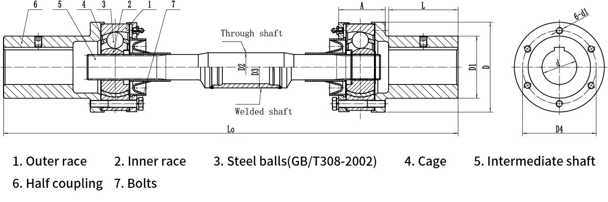
QWL Type Ball Cage Universal Coupling
The QWL-series ball-cage universal coupling is a power transmission component that combines high precision with constant-velocity transmission characteristics. Its core advantage lies in its ability to maintain perfectly synchronous, constant-velocity rotation between the driving and driven shafts, even when there is an angular misalignment or slight displacement; this performance significantly surpasses that of standard cross-shaft universal couplings. Torque is transmitted via the pure rolling motion of precision steel balls between the cage windows and the raceways.
The series offers nominal torque ratings ranging from 180 N·m to 10,000 N·m and swing diameters between 85 mm and 275 mm, while supporting maximum angular misalignments of 14° to 18°. Thanks to its symmetrical raceway design and stable mechanical structure, the QWL coupling offers robust impact resistance while effectively eliminating speed fluctuations and vibrations during transmission. Widely used in applications requiring exceptional transmission precision—such as metallurgical rolling mill roller tables, CNC machine tool spindles, precision conveyor lines, and the slewing mechanisms of construction machinery—it serves as an ideal connection solution for achieving high-precision motion control under heavy-load operating conditions.

- Product Parameters
- Send Message
TECHNICAL PARAMETERS
| Type | Nominal torque Tn/N・m |
Allowable maximum shaft inclination angle βmax(°) |
Shaft hole diameter d (H7) |
shaft hole length L |
D | L0 min |
Total length ΔL0 |
A | D1 | D2 | D3 | D4 | Bolt Diameter d1 |
Moment of inertia I/kg·m2 |
Mass m/kg |
|||||||||
| L0 min |
per 100 increment |
L0 min |
per 100 increment |
|||||||||||||||||||||
| Stationary state |
Operating state |
Y | J | Through shaft |
Welded shaft |
Through shaft |
Welded shaft |
Through shaft |
Welded shaft |
Through shaft |
Welded shaft |
Through shaft |
Welded shaft |
|||||||||||
| QWL1 | 180 | 16 | 14 | 25 | 62 | 44 | 85 | 284 | 392 | 24 | 48 | 55 | 20 | 50 | 66 | M8 | 0.0019 | 0.00216 | 0.0001 | 0.00029 | 3.94 | 4.68 | 0.25 | 0.55 |
| 28 | ||||||||||||||||||||||||
| 30 | 82 | 60 | ||||||||||||||||||||||
| 32 | ||||||||||||||||||||||||
| 35 | ||||||||||||||||||||||||
| QWL2 | 355 | 16 | 14 | 32 | 82 | 60 | 100 | 394 | 478 | 32 | 56 | 66 | 30 | 50 | 80 | M8 | 0.00511 | 0.00535 | 0.0006 | 0.00029 | 7.21 | 7.92 | 0.56 | 0.55 |
| 35 | ||||||||||||||||||||||||
| 38 | 112 | 84 | ||||||||||||||||||||||
| 40 | ||||||||||||||||||||||||
| 45 | ||||||||||||||||||||||||
| QWL3 | 800 | 18 | 16 | 45 | 112 | 84 | 130 | 443 | 561 | 40 | 68 | 90 | 31.5 | 60 | 106 | M10 | 0.01899 | 0.01964 | 0.00008 | 0.00052 | 14.69 | 19.02 | 0.61 | 0.68 |
| 48 | ||||||||||||||||||||||||
| 50 | ||||||||||||||||||||||||
| 55 | ||||||||||||||||||||||||
| 56 | ||||||||||||||||||||||||
| 60 | 142 | 107 | ||||||||||||||||||||||
| 63 | ||||||||||||||||||||||||
| 65 | ||||||||||||||||||||||||
| 70 | ||||||||||||||||||||||||
| QWL4 | 1400 | 18 | 16 | 55 | 112 | 84 | 150 | 537 | 643 | 48 | 80 | 105 | 44.5 | 76 | 124 | M12 | 0.04438 | 0.04638 | 0.00029 | 0.00111 | 25.06 | 27.42 | 1.19 | 0.88 |
| 56 | ||||||||||||||||||||||||
| 60 | 142 | 107 | ||||||||||||||||||||||
| 63 | ||||||||||||||||||||||||
| 65 | ||||||||||||||||||||||||
| 70 | ||||||||||||||||||||||||
| 71 | ||||||||||||||||||||||||
| 75 | ||||||||||||||||||||||||
| QWL5 | 2240 | 18 | 16 | 63 | 142 | 107 | 175 | 574 | 714 | 54 | 92 | 120 | 50 | 89 | 140 | M16 | 0.11238 | 0.11663 | 0.00048 | 0.00183 | 36.32 | 40.17 | 1.54 | 1.04 |
| 65 | ||||||||||||||||||||||||
| 70 | ||||||||||||||||||||||||
| 71 | ||||||||||||||||||||||||
| 75 | ||||||||||||||||||||||||
| 80 | 172 | 132 | ||||||||||||||||||||||
| 85 | ||||||||||||||||||||||||
| 90 | ||||||||||||||||||||||||
| QWL6 | 3150 | 18 | 16 | 71 | 142 | 107 | 200 | 675 | 805 | 54 | 103 | 140 | 57.5 | 102 | 159 | M12 | 0.21635 | 0.2236 | 0.00084 | 0.00328 | 55.11 | 59.95 | 2.04 | 1.04 |
| 75 | ||||||||||||||||||||||||
| 80 | 172 | 132 | ||||||||||||||||||||||
| 85 | ||||||||||||||||||||||||
| 90 | ||||||||||||||||||||||||
| 95 | ||||||||||||||||||||||||
| 100 | 212 | 167 | ||||||||||||||||||||||
| 110 | ||||||||||||||||||||||||
| QWL7 | 4500 | 18 | 16 | 80 | 172 | 132 | 220 | 701 | 840 | 54 | 110 | 160 | 63 | 102 | 180 | M12 | 0.348 | 0.3555 | 0.00122 | 0.00328 | 72.34 | 77.54 | 2.45 | 1.42 |
| 85 | ||||||||||||||||||||||||
| 90 | ||||||||||||||||||||||||
| 95 | ||||||||||||||||||||||||
| 100 | 212 | 167 | ||||||||||||||||||||||
| 110 | ||||||||||||||||||||||||
| 120 | ||||||||||||||||||||||||
| QWL8 | 6300 | 20 | 18 | 90 | 172 | 132 | 245 | 710 | 910 | 60 | 124 | 180 | 76 | 14 | 197 | M16 | 0.584 | 0.618 | 0.00257 | 0.01138 | 96.92 | 109.97 | 3.56 | 2.6 |
| 95 | ||||||||||||||||||||||||
| 100 | 212 | 167 | ||||||||||||||||||||||
| 110 | ||||||||||||||||||||||||
| 120 | ||||||||||||||||||||||||
| 125 | ||||||||||||||||||||||||
| 130 | 252 | 202 | ||||||||||||||||||||||
| 140 | ||||||||||||||||||||||||
| QWL9 | 10000 | 20 | 18 | 100 | 212 | 167 | 275 | 842 | 1065 | 70 | 173 | 205 | 81 | 140 | 226 | M16 | 1.26225 | 1.298 | 0.00331 | 0.01138 | 148.36 | 162.84 | 4.04 | 2.6 |
| 110 | ||||||||||||||||||||||||
| 120 | ||||||||||||||||||||||||
| 125 | ||||||||||||||||||||||||
| 130 | 252 | 202 | ||||||||||||||||||||||
| 140 | ||||||||||||||||||||||||
| 150 | ||||||||||||||||||||||||
| 160 | 302 | 242 | ||||||||||||||||||||||
Note:
1. Nominal torque at a rotational speed of n = 100 r/min. Calculated value when the shaft inclination angle is 0°.
2. The short-term overload torque generated during starting and braking (Tmax) is 3 times the normal torque (Tn), and the duration must not exceed 15 seconds.


")
")

")
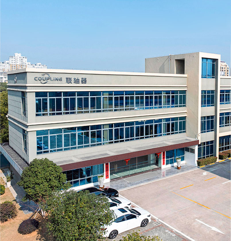
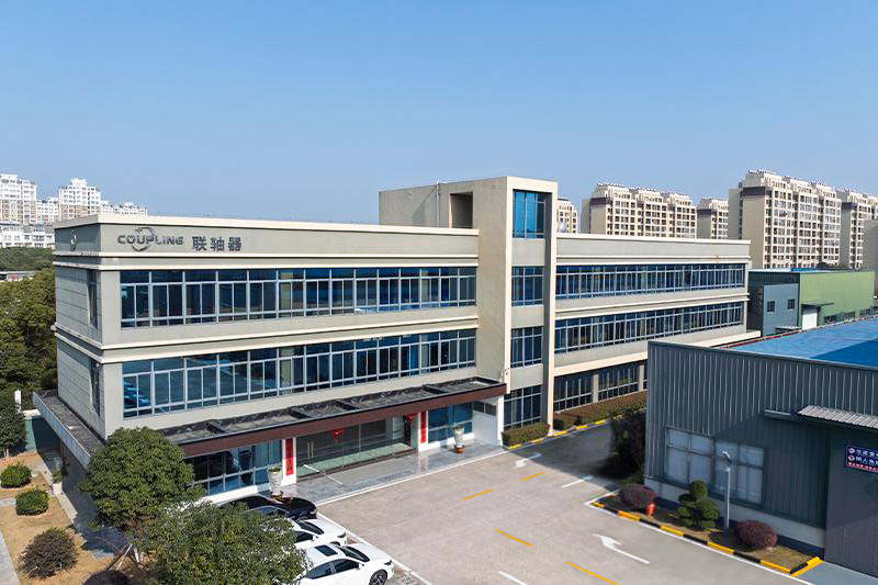
Zhongye Heavy Industry Technology (Zhenjiang) Co., Ltd.
Zhongye Heavy Industry Technology (Zhenjiang) Co., Ltd. is located in a well-known ancient city, Zhenjiang. We are an enterprise integrating R & D, manufacturing, and sales. As a famous China Ball Cage/Retainer/Drive Coupling Manufacturers and Constant Velocity Coupling/CV Coupling Suppliers, our products are widely used in metallurgical equipment, mining equipment, water equipment, lifting equipment, paper equipment, port equipment and other industries.
Our main products are toothed coupling, elastic sleeve column pin coupling, elastic column pin coupling, gear coupling with elastic pin, a universal coupling, tire coupling, jaw coupling, star coupling, diaphragm coupling, drum coupling and grid coupling, the Oldham coupling, flange coupling, clip shell coupling, GL type roller chain coupling and a safety coupling, and so on. Our company also undertakes a variety of non-standard coupling designs and manufacturing.
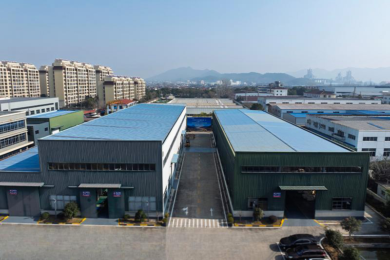
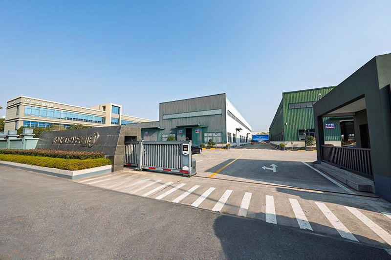
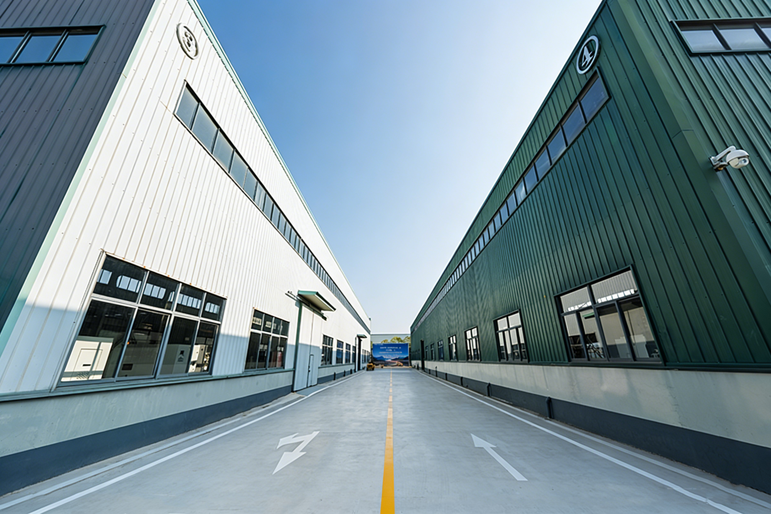
New workshop covers an area of about 16463.52m². heavy workshop 5,500 M2, Precision workshop 4,600m², office building and the gymnasium 2000 M2, Dinning hall 500m², Warehouse 1000m², Roads, greening, parking areas 3563 M2.
View more
Our main products are toothed coupling, elastic sleeve column pin coupling, elastic column pin coupling, gear coupling with elastic pin, a universal coupling, tire coupling, jaw coupling, star coupling, diaphragm coupling, drum coupling and grid coupling, the Oldham coupling, flange coupling, clip shell coupling, GL type roller chain coupling and a safety coupling, and so on. Our company also undertakes a variety of non-standard coupling designs and manufacturing.
New workshop covers an area of about 16463.52m². heavy workshop 5,500 M2, Precision workshop 4,600m², office building and the gymnasium 2000 M2, Dinning hall 500m², Warehouse 1000m², Roads, greening, parking areas 3563 M2.
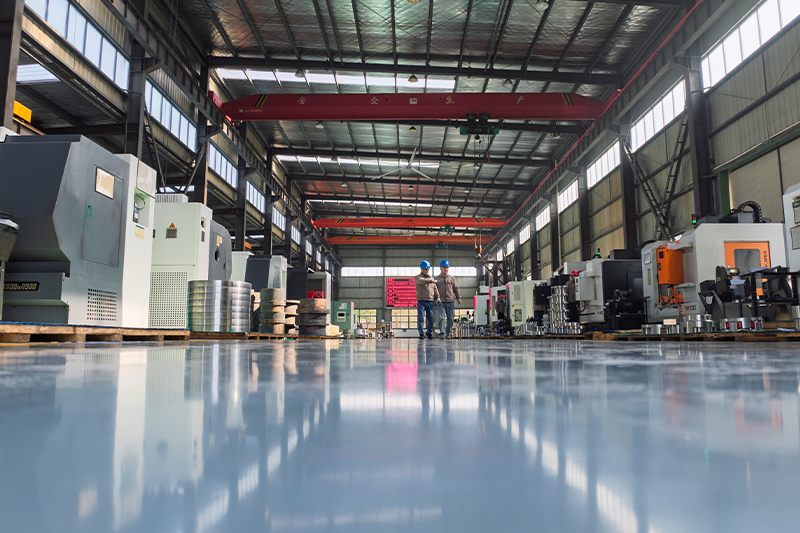
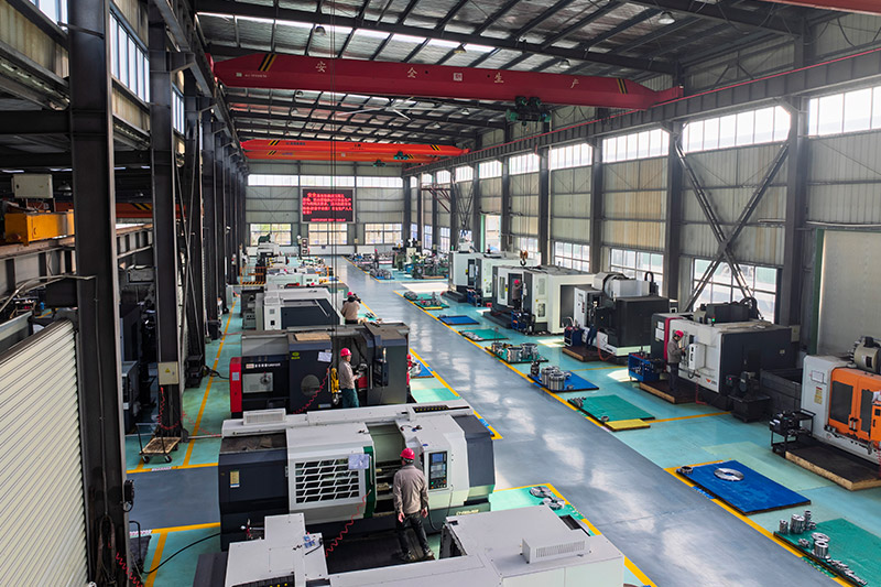
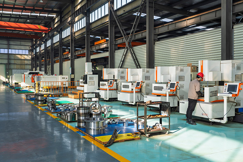
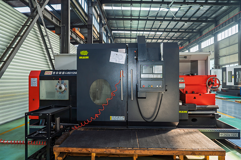
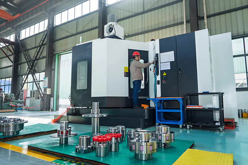
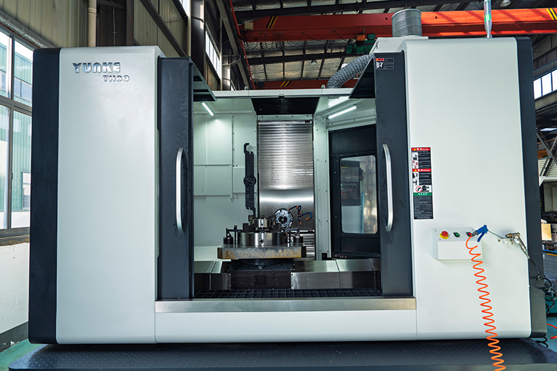
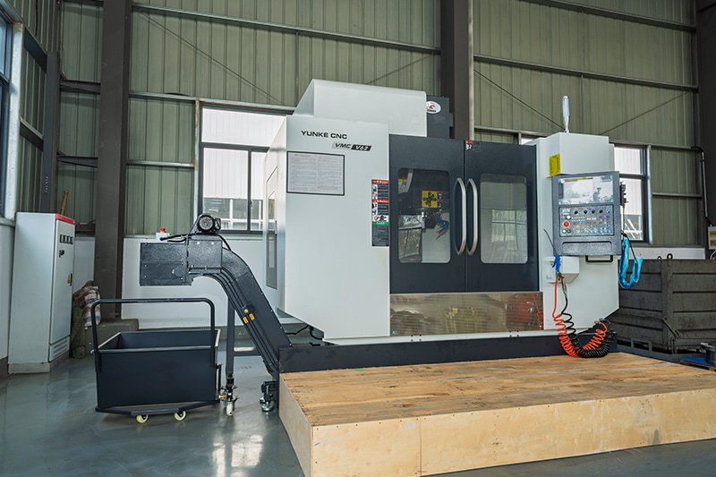
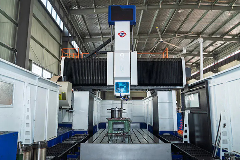
Plant Equipment
FACTORY TOUR
Get In Touch
Follow us
- Quick Links
- About
- Products
- Our Service
- News & Events
- Contact
- Products Series
- Flexible Couplings with Non-Elastic Elements
- Flexible Couplings with Metal Elastic Elements
- Flexible Couplings with Non-Metallic Elastic Elements
- Safety Coupling
- Rigid Coupling
- Contact Us
- Tel: +86 511 8572 3800 +86 511 8572 3900
- Mobile: +86 15106109009
- Email: [email protected]
- Add:No.1 Zhongye Yingbin Avenue, Gaozi Street, Dantu Economic Development Zone, Zhenjiang City, Jiangsu Province, China.


