:+86 15106109009
:sales@couplingzy.com


 English
  русский
  Español
  عربى
عربى  Português
  Deutsch
  Türk
Türk  Indonesia

Coupling Selection Calculation: How to Size Drive Shaft Couplings Correctly
Content
- 1 Why Coupling Selection Calculation Is the First Step
- 2 Step 1: Calculate the Rated Torque
- 3 Step 2: Apply a Service Factor to Get the Design Torque
- 4 Step 3: Check Shaft Diameter, Bore, and Keyway Limits
- 5 Step 4: Evaluate Misalignment, Speed, and Environment
- 6 Step 5: Compare Coupling Types and Confirm the Final Selection
- 7 Common Mistakes in Coupling Selection Calculation
A 55 kW conveyor motor trips its overload relay three times within a week, and the maintenance team finds a cracked coupling hub on the second inspection. The usual response is to order the same coupling again, but the root cause is often a selection that was never checked against the actual duty. Coupling selection calculation exists to prevent this situation: it converts motor power, speed, shaft geometry, and load character into a design torque value, and that value tells you whether a coupling is fit for the application.
Why Coupling Selection Calculation Is the First Step
An incorrect calculation fails in two directions. An undersized coupling eventually cracks, wears, or loses its elastic elements because it operates above its rated torque capacity for prolonged periods. An oversized coupling looks safe but brings different penalties: higher rotational inertia, a larger envelope that complicates installation, greater cost, and sometimes additional unbalance at high speed. The goal is not to choose the biggest model in the catalog, but the smallest one that meets all torque, bore, speed, and misalignment limits with an acceptable safety margin.
Calculation also protects procurement discipline. When a coupling is selected from a catalog by shaft size alone, design torque is never confirmed. When it is selected with a service factor but without a misalignment check, premature wear still occurs. Running the numbers in a consistent sequence — torque, service factor, geometry, speed, misalignment, environment — is the difference between a coupling installed once and a coupling replaced several times over the equipment's life.
Step 1: Calculate the Rated Torque
The starting point of any coupling selection calculation is the steady-state torque transmitted at the operating speed. In metric units:
Ta = 9550 × P / n
where Ta is the rated torque in N·m, P is the transmitted power in kilowatts, and n is the shaft speed in revolutions per minute. In imperial units, the equivalent is T = 5252 × HP / RPM, with torque in lb·ft. For a 55 kW motor running at 1475 rpm, Ta = 9550 × 55 / 1475 ≈ 356 N·m. This is the base value that every subsequent step modifies.
Step 2: Apply a Service Factor to Get the Design Torque
Real drives do not run at a perfectly constant load. Starting torque, load spikes, frequent reversals, and process irregularity all create torque peaks above the steady-state value. The standard way to capture these peaks is the service factor K. The design torque becomes:
Td = Ta × K
The table below summarizes representative service factors for common driven machine classes.
| Driven machine class | Typical examples | Service factor K |
|---|---|---|
| Uniform load | Centrifugal pumps, fans, light conveyors | 1.0 – 1.25 |
| Moderate shock | Screw conveyors, agitators, presses | 1.25 – 1.75 |
| Heavy shock | Crushers, mills, reciprocating compressors, cranes | 1.75 – 2.5 |
Two practical points. First, the service factor multiplies the rated torque; it does not replace a direct check of peak torque when the application specifies a known maximum value. Second, when the driver is an internal combustion engine rather than an electric motor, most coupling manufacturers recommend raising K by 0.25 to 0.5 because engine torque delivery is more irregular.
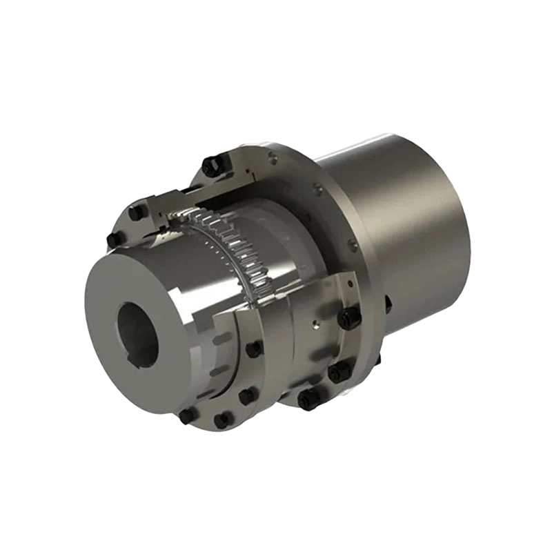
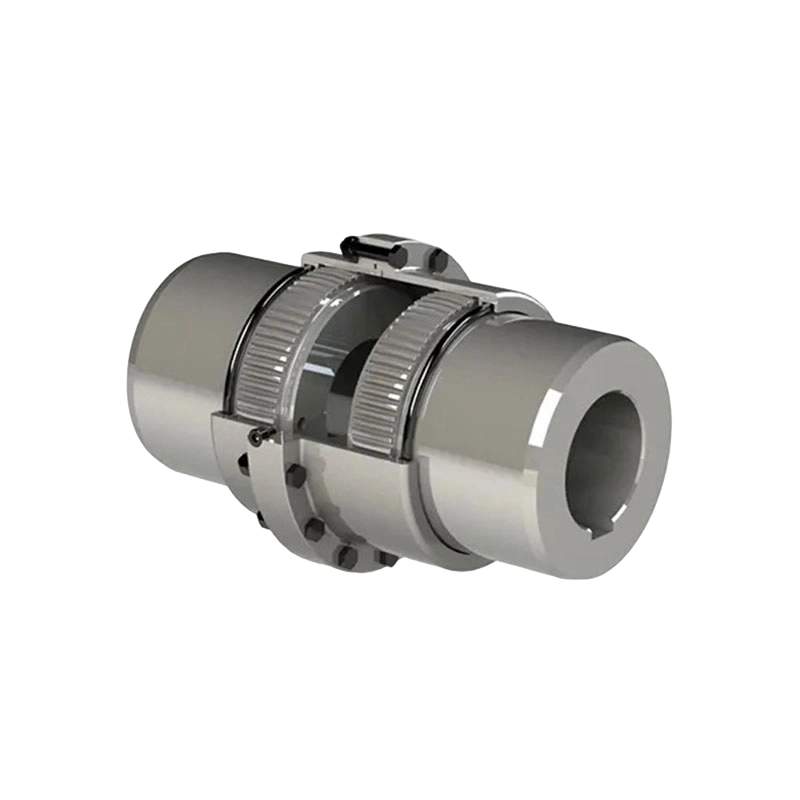
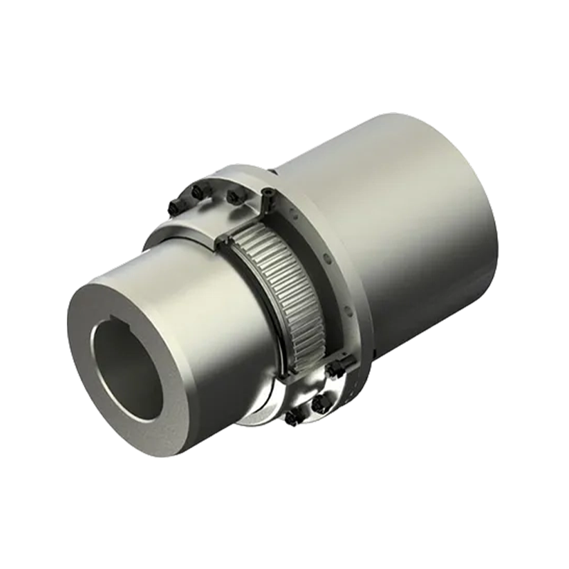
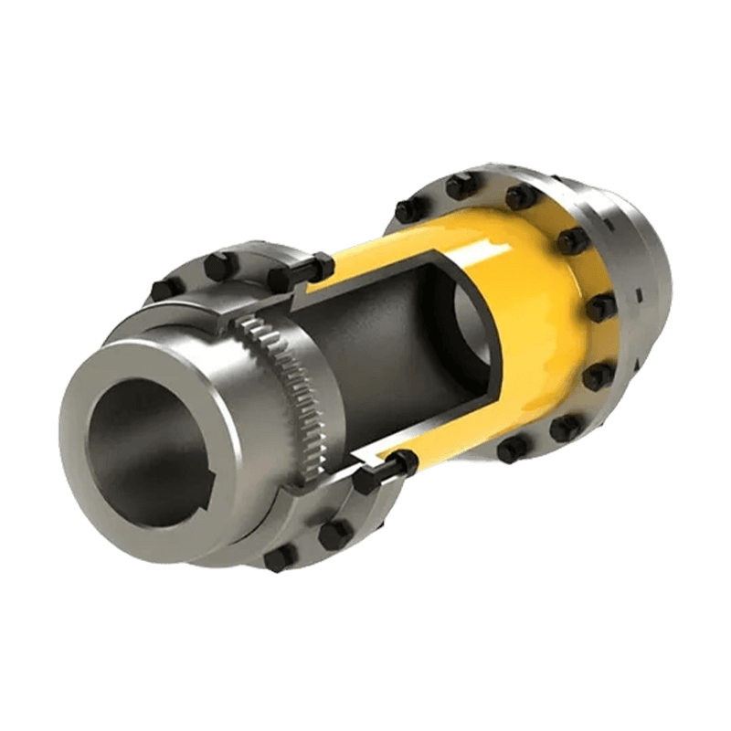
For heavy shock duties where the design torque reaches high values, the coupling family must deliver proven torque capacity and structural margin. Drum gear couplings are a common answer in metallurgical and mining drives.
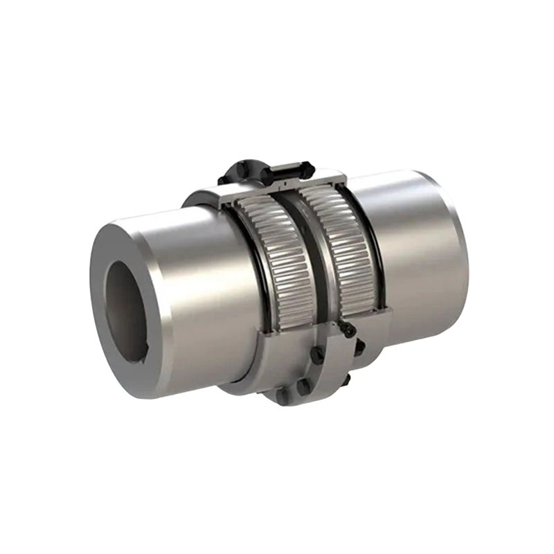 GB Drum Gear Coupling for Heavy-Duty Shock LoadsThis drum gear coupling from MCC Heavy Industry delivers robust torque capacity and impact resistance, making it a reliable choice for metallurgical and mining drives where design torque reaches high values.View Product →
Step 3: Check Shaft Diameter, Bore, and Keyway Limits
Torque defines the load, but the shaft defines the geometry. Every coupling model has a standard bore range, and both shaft diameters must fall inside it. If the shaft is close to the upper edge of one model's bore range, the next size up is usually required even when the torque calculation would allow a smaller model. This is one of the most common geometry-driven upgrades in coupling selection calculation.
Keyway connections also deserve attention. In reversing or high-torque applications, standard key dimensions are normally sufficient, but keyway shear stress should be verified when the coupling transmits torque near its catalog limit. For vertical or high-vibration installations, consult the manufacturer's guidance on hub clamping and axial retention.
Step 4: Evaluate Misalignment, Speed, and Environment
Machined shafts are never perfectly aligned, and the coupling is the component that absorbs the residual displacement. Three values should be quantified: angular misalignment in degrees, parallel offset in millimeters, and axial displacement in millimeters. Each coupling family handles these three components differently, so misalignment requirements often determine the coupling type before the final size is chosen.
Diaphragm couplings, for example, accommodate moderate angular and parallel misalignment while providing high torsional stiffness and no wearing parts. They suit high-speed and precision drives where lubrication access is limited. A single-disc elastic diaphragm coupling covers most standard motor-to-machine connections, while double-disc or intermediate-shaft versions handle longer spans and higher offsets.
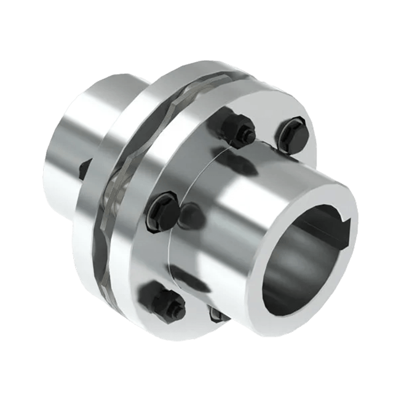 DMA Single-Type Elastic Diaphragm Coupling for Precision DrivesThis diaphragm coupling offers high torsional stiffness, zero backlash, and lubrication-free operation, suiting high-speed precision systems where moderate misalignment compensation and minimal maintenance are required.View Product →
Speed is the next constraint. Maximum permissible speed depends on the coupling's outside diameter and balance quality. A large elastomeric coupling can be torque-sufficient but speed-limited because its elastic element deforms under centrifugal force. Gear and diaphragm couplings must be checked against their catalog speed limits as well, including the overspeed trip setting where applicable.
Environmental conditions influence material selection. Elastomeric elements typically have upper temperature limits in the 80–120 °C range depending on the polymer, whereas all-metal couplings tolerate considerably higher temperatures. In dusty, humid, or chemically aggressive atmospheres, lubrication interval and maintenance access become selection criteria rather than afterthoughts.
Step 5: Compare Coupling Types and Confirm the Final Selection
Once design torque, bore size, speed, misalignment, and environmental limits are fixed, the coupling family can be shortlisted. The table below summarizes the main categories used in industrial drives.
| Coupling type | Torque capacity | Misalignment capacity | Vibration damping | Typical applications |
|---|---|---|---|---|
| Drum gear coupling | High | Moderate | Low | Heavy industry, high torque |
| Diaphragm coupling | High | Moderate | Low | High speed, precision drives |
| Elastomeric pin or plum coupling | Moderate | Moderate | High | General machinery, motor drives |
| Tire coupling | Moderate | High | High | Shock loads, high misalignment |
| Universal joint coupling | High | High angular | None | Angular transmission, long spans |
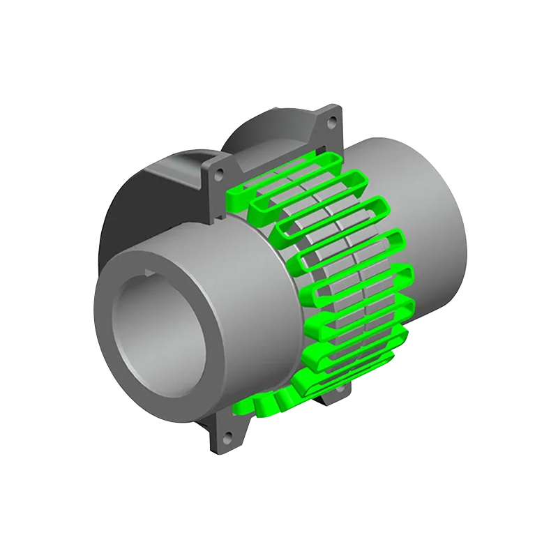
For general machinery driven by an electric motor, elastomeric couplings offer good damping, easy installation, and minimal maintenance. A plum-shaped elastic coupling, for instance, absorbs vibration and is tolerant of small misalignments, which makes it a practical default for fans, pumps, and light conveying systems.
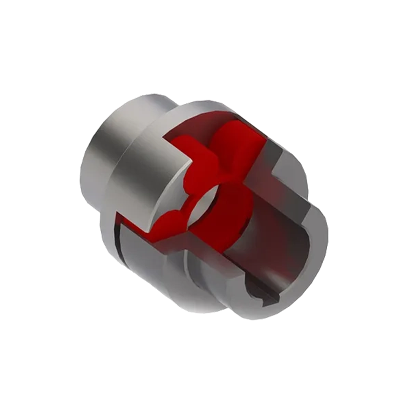 MC Plum-Shaped Elastic Coupling for General MachineryA versatile elastomeric coupling with vibration damping and easy installation, ideal for fans, pumps, and light conveying systems. Its wide torque and speed ranges accommodate various motor-driven applications.View Product →
After the coupling family is chosen, confirm the model by entering the design torque and actual bore sizes into the manufacturer's catalog. The model's rated torque must be equal to or greater than Td, and the bore range must accept both shaft diameters. For lifting and crane applications, also verify whether a brake wheel or brake disc must be integrated into the coupling.
Common Mistakes in Coupling Selection Calculation
- Using rated torque without a service factor. This is the leading cause of premature failure in shock-loaded equipment.
- Selecting by shaft diameter only. A coupling that fits the bore may be far below the required torque rating.
- Ignoring the maximum speed limit. Some elastomeric and gear couplings are torque-correct but speed-incorrect.
- Applying a single misalignment value to all coupling types. Angular, parallel, and axial capacities are independent for every product family.
- Overlooking brake wheel or brake disc requirements in lifting equipment.
- Reusing a coupling code from an identical-looking machine without confirming the actual drive parameters.
In practice, a coupling selection calculation does not replace the manufacturer's catalog. It defines what to look for in that catalog: the design torque value, bore range, speed limit, and misalignment capacity. The complete sequence can be summarized as follows:
- Calculate the rated torque from power and speed.
- Apply the service factor to obtain the design torque.
- Verify shaft diameter, bore range, and keyway limits.
- Confirm speed, misalignment, and environmental constraints.
- Select the coupling family and confirm the catalog model against Td.
Once these numbers are fixed, comparing models becomes straightforward and the risk of premature field failure drops significantly.
If the duty falls outside standard catalog ranges — an unusual bore, a long span requiring an intermediate shaft, or a special brake configuration — the right approach is to let an experienced coupling manufacturer review the complete drive envelope. Calculating with conservative input values first shortens the engineering discussion and makes lead times more predictable. The guide on how to select the appropriate coupling covers additional application considerations, and the advantages of working with a specialized manufacturer apply to the final validation step.

- Quick Links
- About
- Products
- Our Service
- News & Events
- Contact
- Products Series
- Flexible Couplings with Non-Elastic Elements
- Flexible Couplings with Metal Elastic Elements
- Flexible Couplings with Non-Metallic Elastic Elements
- Safety Coupling
- Rigid Coupling
- Contact Us
- Tel : +86 511 8572 3800 +86 511 8572 3900
- Mobile : +86 15106109009
- Email : sales@couplingzy.com
- Add:No.1 Zhongye Yingbin Avenue, Gaozi Street, Dantu Economic Development Zone, Zhenjiang City, Jiangsu Province, China.


