:+86 15106109009
:sales@couplingzy.com


 English
  русский
  Español
  عربى
عربى  Português
  Deutsch
  Türk
Türk  Indonesia

How Can You Choose the Right Flexible Coupling for Misalignment Compensation?
Content
- 1 Misalignment Is Not a Single Number
- 2 How the Elastic Element Determines Compensation Behavior
- 3 The Torque Calculation That Comes First
- 4 Stiffness: The Choice People Forget Until a Bearing Overheats
- 5 A Selection Sequence That Works in a Plant Environment
- 6 Mistakes That Show Up in Maintenance Reports Later
- 7 Sector Conditions Worth Confirming
Two similar pump sets can follow very different maintenance histories: one keeps its bearings for years, the other runs hot and noisy within months. The difference rarely shows on the commissioning alignment sheet. It appears in the coupling selection, specifically in whether the flexible coupling can absorb the misalignment that shows up when the shaft train is warm and loaded, without pushing excessive reaction forces into the bearings. That is the real test when choosing flexible couplings for misalignment compensation.
Selection is not about taking a high torque rating in the catalogue. It is about matching stiffness, compensation range and maintenance needs to one shaft train: quantify the misalignment pattern first, then check torque, speed, space and service access in that order.
Misalignment Is Not a Single Number
Most misalignment is a combination of three components: parallel offset, angular misalignment and axial displacement. Laser alignment reports record the cold, static condition. Once the motor and driven machine reach operating temperature, thermal growth, pipe strain and baseplate settlement change the relative shaft positions.
| Component | What it looks like | Typical source |
|---|---|---|
| Parallel offset | Shaft centerlines are parallel but do not coincide | Baseplate settlement, motor shim changes, differential thermal growth |
| Angular misalignment | Shaft centerlines meet at an angle | Uneven flange runout, pipe strain, distorted frame |
| Axial displacement | Shafts move toward or away from each other | Thermal expansion of the shaft train, thrust loads |
Each component needs to be quantified in cold and hot conditions, because the coupling sees the operating value rather than the installation value. A practical rule is to keep the expected steady-state misalignment below half of the rated allowable value wherever possible.
How the Elastic Element Determines Compensation Behavior
Flexible couplings compensate misalignment in three fundamentally different ways: metallic elements bend, elastomeric elements shear and compress, and mechanical joints slide or roll. The difference defines stiffness, service life, maintenance interval and failure mode.
| Criterion | Metal elastic | Non-metal elastic | Mechanical (gear/universal) |
|---|---|---|---|
| Torsional stiffness | High and stable | Low to moderate, non-linear | High |
| Damping of shock | Low | High | Very low |
| Misalignment capacity | Moderate | Large | Large |
| Maintenance | Little or none | Replace element periodically | Lubrication and wear checks |
Metal Elastic Elements: Stiffness That Stays Predictable
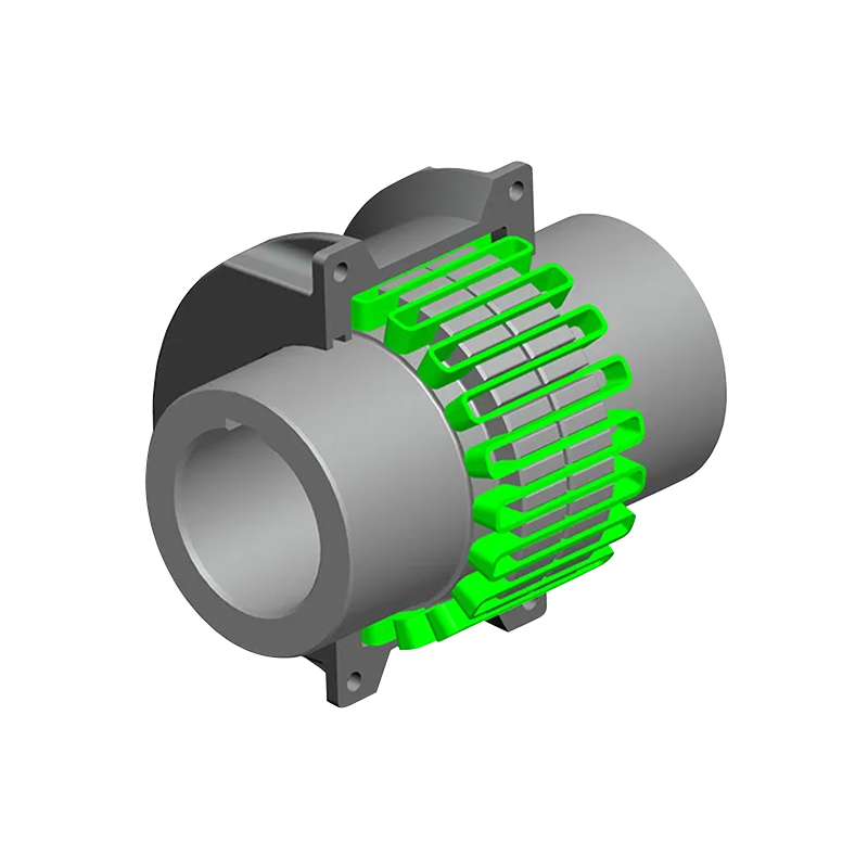
Diaphragm and snake-spring couplings belong to this group. Metal elastic elements deform in a predictable way, so their stiffness changes little with temperature and speed, and there is no sliding contact to wear inside the compensation function. That makes them the normal choice for continuous process lines and higher-speed shafts. The compensation envelope is smaller than an elastomer's, and good final alignment is still required during installation. The reward is a long service life with very little routine maintenance.
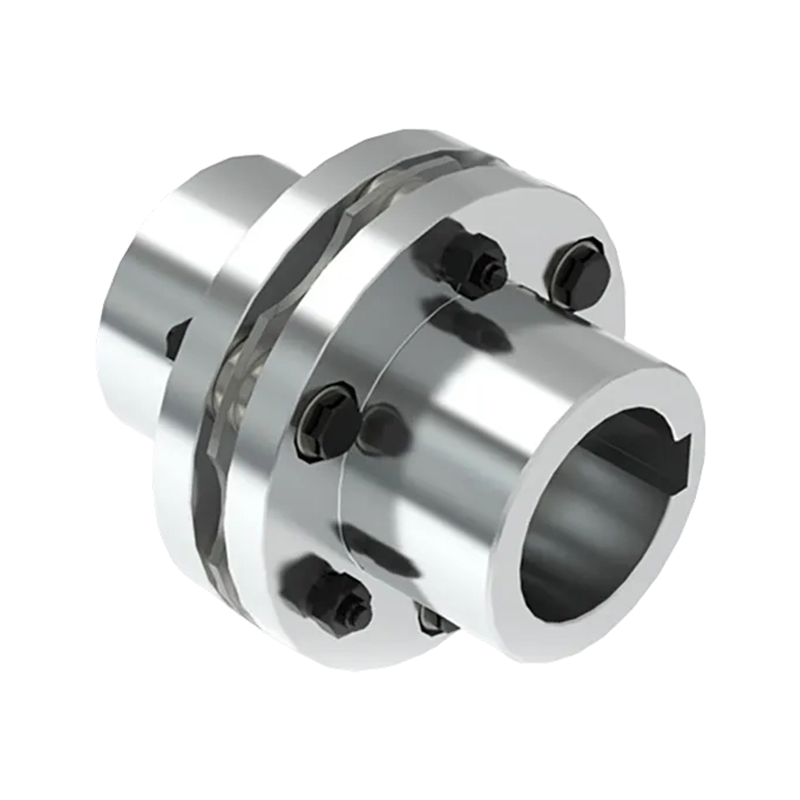
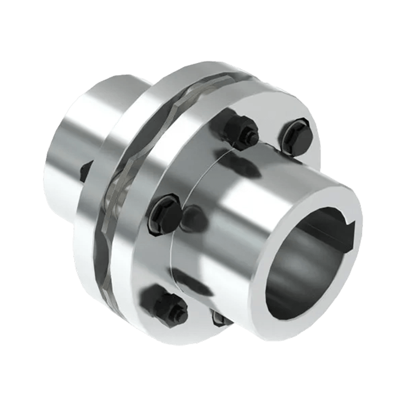 DMA Single Type Elastic Diaphragm CouplingA precision metal elastic coupling offering high torsional rigidity and zero backlash for high-speed operation, suitable for continuous process lines where minimal maintenance and long service life are expected.View Product →
Non-Metal Elastic Elements: Damping and Elastomer Limits
Tire, plum, star and elastic-pin couplings use rubber or polyurethane elements. Their main strength is damping: they reduce shock peaks from crushers, reciprocating machines and frequent starts, and they provide electrical insulation between driver and driven equipment. The limitation is life expectancy. Continuous operation above roughly 80 to 100 °C accelerates ageing, and oil, ozone and chemicals reduce elastomer life faster than torque does. The element should be treated as a consumable, not a permanent part.
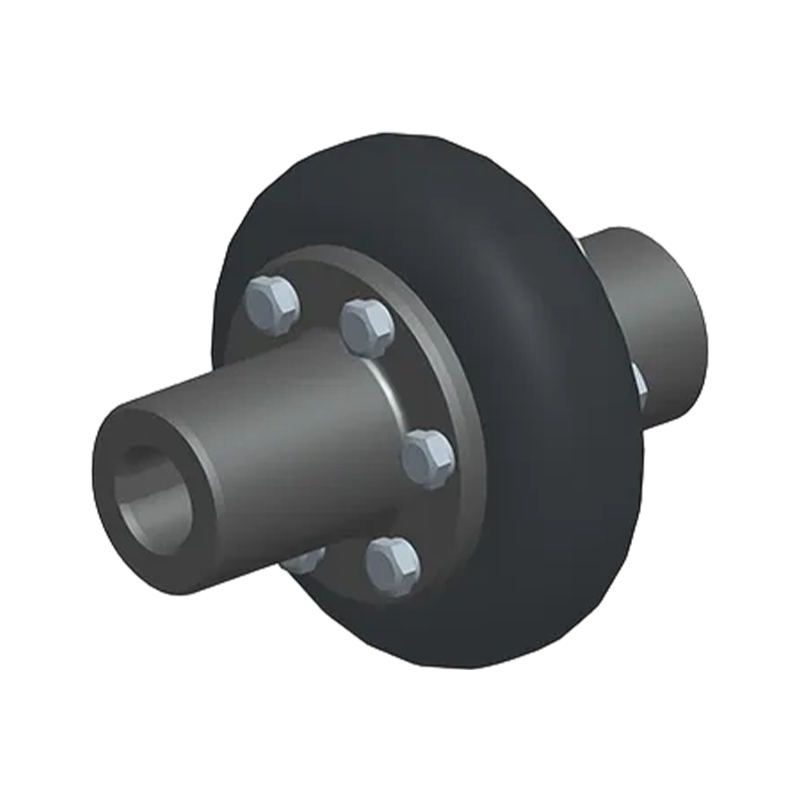 LCA Type Tire CouplingA highly elastic, shock-absorbing coupling with a frameless radial-cut tire body, providing strong misalignment compensation and lubrication-free operation, ideal for heavy machinery in harsh environments.View Product →
Mechanical Compensation: Capacity Without Elastic Elements
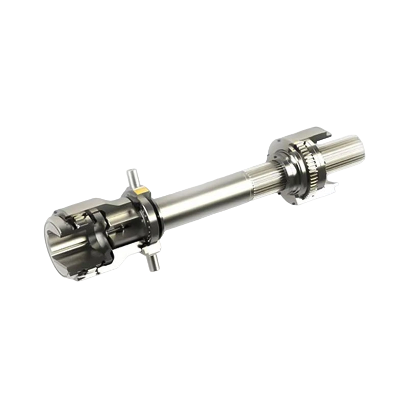
Drum gear couplings, universal shafts and slider couplings rely on machined surfaces and mechanical clearance instead of elastic deformation. This group handles very high torque in a compact envelope and is often the only answer for rolling mills, kiln drives and crane travel. Angular compensation can be large, but no shock damping is provided. Lubrication and wear checks are part of the service schedule, while stiffness stays high throughout the life of the joint.
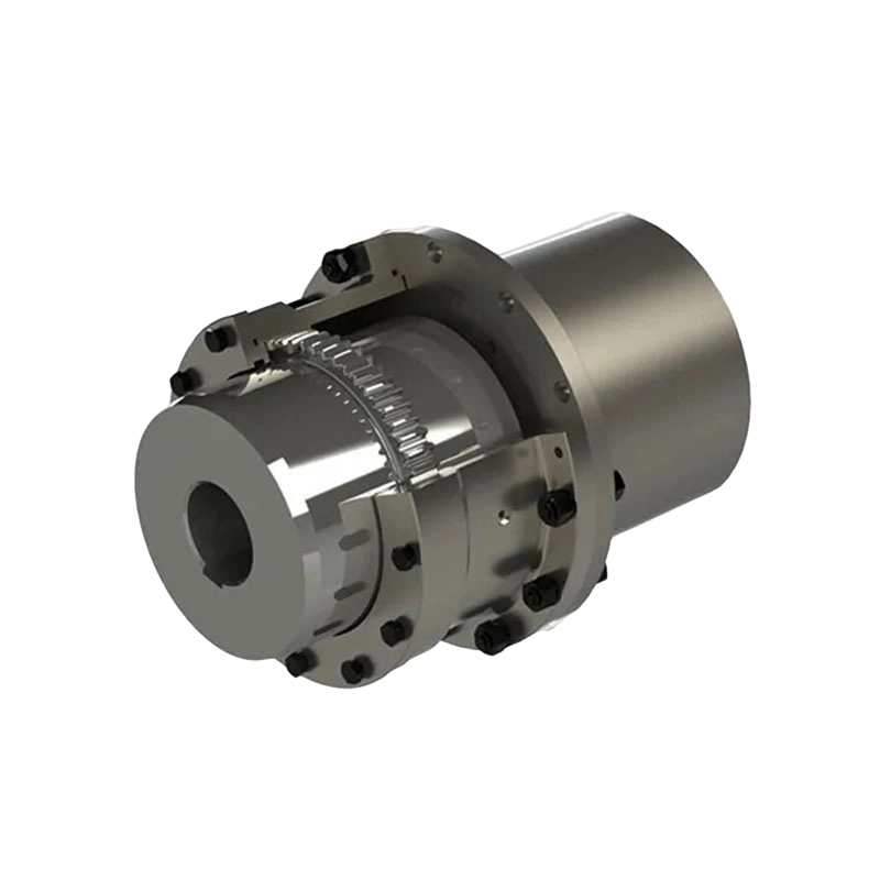
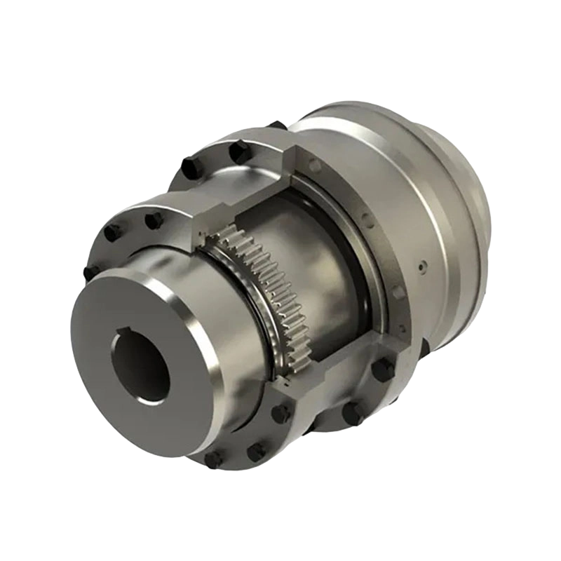 GA Drum Gear CouplingA robust high-torque gear coupling with drum-shaped teeth for comprehensive shaft misalignment compensation, designed for heavy-duty industrial drives that require backlash-free power transmission.View Product →
The Torque Calculation That Comes First
The motor nameplate torque is only the starting point. Design torque is the nameplate value multiplied by an application service factor covering start frequency, shock loads, reversing duty and driven inertia. If the motor can develop locked-rotor torque, the coupling must survive that transient as well.
For example, a 150 kW motor at 1480 r/min has a rated torque of about 968 N·m (9,549 × 150 / 1,480). With a service factor of 1.75 for moderate shock loading, the selection torque becomes about 1,700 N·m. If the starting torque reaches twice rated, the peak approaches 3,400 N·m. Check peak capacity, not just average duty, and expect a good supplier to ask about the driven load rather than only the motor power.
Stiffness: The Choice People Forget Until a Bearing Overheats
Torsional stiffness controls how much angular deflection the coupling shows under load. Printing rolls, servo axes and grinding spindles need high stiffness to hold synchronism. Diesel drives, crushers and fans often benefit from lower stiffness, which shifts shock away from the gearbox.
The less obvious parameter is axial and bending stiffness. A diaphragm coupling can impose a noticeable axial force if the shafts move toward or away from each other, and that force must be carried by the motor or gearbox bearing. An elastomer coupling is axially softer, but its stiffness rises quickly under torque because rubber behaves non-linearly. Check torsional stiffness, damping and reaction forces against the allowable bearing loads of the connected machines.
A Selection Sequence That Works in a Plant Environment
The following order keeps the data in the sequence the coupling actually experiences.
- Measure the available space: shaft diameters, shaft end distance, hub length, plus any brake wheel or brake disc that must share the axial envelope.
- Define the torque cycle: rated torque, peak torque, start frequency and reversing duty set the service factor.
- Quantify the three misalignment components in cold and hot conditions, and confirm the installation tolerance the plant can realistically hold.
- Check speed and inertia. Balancing grade and moment of inertia may govern the choice on high-speed shafts.
- Select the compensation principle: damping, synchronous stiffness or large angular capacity.
- Review reaction forces and maintenance access so bearings are not overloaded and wearing parts can be reached.
These steps are also covered in our engineering note on how to select the appropriate coupling, which follows the same workflow in more detail.
Mistakes That Show Up in Maintenance Reports Later
A few selection mistakes recur in maintenance reports.
- Choosing on rated torque only. The nameplate value hides the start-up peaks that crack hubs or melt elastomers.
- Treating peak compensation as a continuous operating point. Running at full misalignment shortens coupling life and adds a steady load to bearings.
- Ignoring the elastomer temperature ceiling. A coupling that works in the workshop can fail beside a furnace.
- Forgetting maintenance access. If the crew cannot reach the element or lubrication point, they will not maintain it.
- Making the coupling stiffer to "solve" vibration. A stiffer coupling can move torsional resonance into a more dangerous frequency range.
Sector Conditions Worth Confirming
In metallurgical plants, heat radiated from furnaces restricts elastomer use. Drum gear couplings and universal shafts dominate, and their lubrication schedule must fit a narrow shutdown window.
In mining, shock loads and dust are the primary concerns. Tire and elastic-pin couplings are common because the element can be replaced quickly, provided sealing keeps dust and moisture away from the working surfaces.
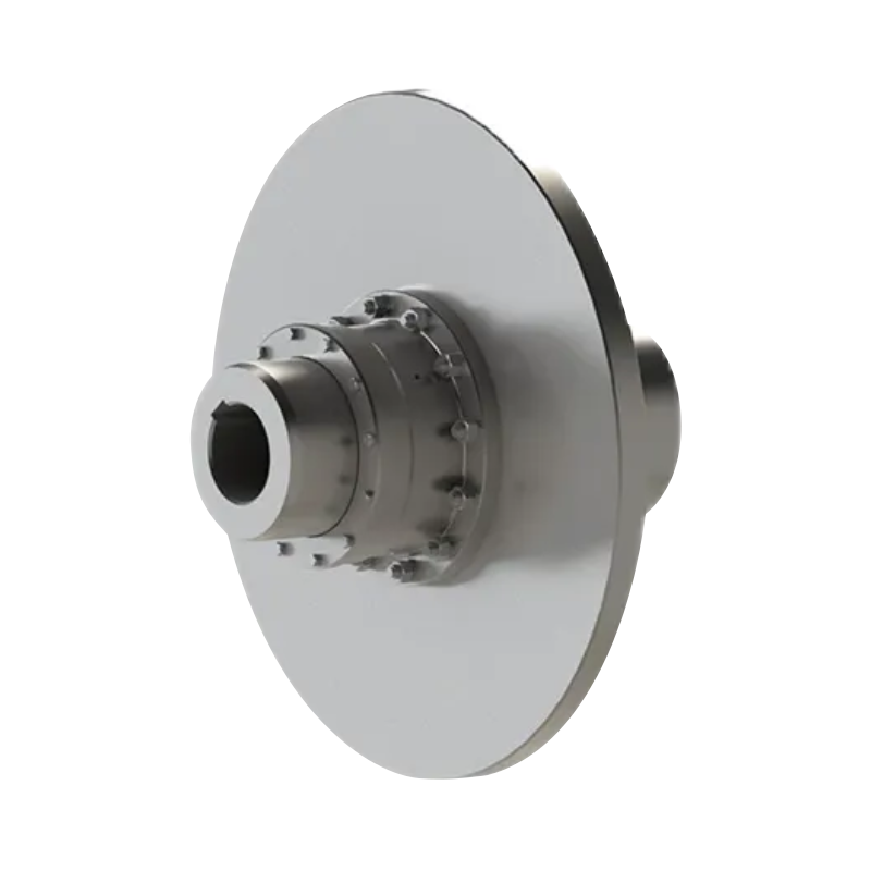
Crane and port equipment usually integrates a brake wheel or brake disc, which fixes the axial space. A standard catalogue coupling often needs hub or flange adjustment to fit the hoist geometry.
Paper machine and water pump drives frequently use spacer couplings with an intermediate shaft. The longer shaft increases sensitivity to the angular setting at each coupling half, so the critical speed of the assembly should be checked rather than assumed.
Choosing a flexible coupling for misalignment compensation starts with one practical question: how will the two shafts move relative to each other when the machine is loaded and warm? Quantify that movement, define the torque cycle, and the right coupling family becomes clear. Finish with an operational check: inspection time, element replacement interval and the failure mode the plant will see first.
We can adjust hub length, flange geometry and intermediate-shaft length without moving the motor or the driven equipment. Ask us for reaction forces, balancing grade and elastomer temperature limits in writing. If a standard series does not fit the shaft spacing or brake interface, our non-standard design route exists for exactly that reason. A supplier with genuine engineering and manufacturing capability becomes valuable well before the purchase order is placed.
- Quick Links
- About
- Products
- Our Service
- News & Events
- Contact
- Products Series
- Flexible Couplings with Non-Elastic Elements
- Flexible Couplings with Metal Elastic Elements
- Flexible Couplings with Non-Metallic Elastic Elements
- Safety Coupling
- Rigid Coupling
- Contact Us
- Tel : +86 511 8572 3800 +86 511 8572 3900
- Mobile : +86 15106109009
- Email : sales@couplingzy.com
- Add:No.1 Zhongye Yingbin Avenue, Gaozi Street, Dantu Economic Development Zone, Zhenjiang City, Jiangsu Province, China.


