:+86 15106109009
:sales@couplingzy.com


 English
  русский
  Español
  عربى
عربى  Português
  Deutsch
  Türk
Türk  Indonesia

What Is a Diaphragm Coupling in Ghana's Industrial Drive Systems?
Content
- 1 What Is a Diaphragm Coupling in Ghana's Industrial Drive Systems?
- 2 How Does the MPJ Type Diaphragm Coupling with Intermediate Shaft Differ from Standard Designs?
- 3 What Role Does the Intermediate Shaft Play in Long-Distance Power Transmission?
- 4 What Materials and Manufacturing Steps Are Involved in Producing These Couplings?
- 5 What Performance Characteristics Should Be Expected from This Coupling Type?
- 6 Where Are These Couplings Applied Within Ghana's Industrial Drive Systems?
- 7 What Should Be Reviewed Before Selecting and Installing This Coupling Type?
What Is a Diaphragm Coupling in Ghana's Industrial Drive Systems?
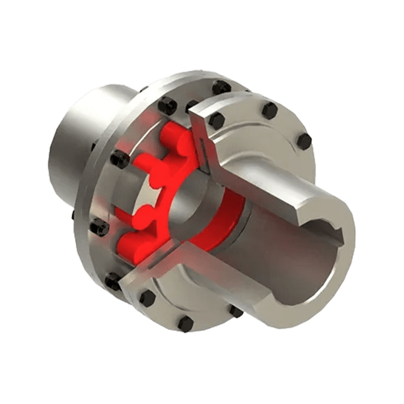
A diaphragm coupling is a mechanical device installed between two shaft ends within an industrial drive system to transmit rotational torque while allowing for a degree of angular, parallel, or axial displacement between them. Rather than relying on rubber inserts or elastomeric sleeves, the coupling uses a thin, contoured metal disc, referred to as the diaphragm, which flexes slightly to accommodate misalignment while the rest of the assembly maintains a rigid metal-to-metal connection. This places the design within the broader group of non-elastic flexible couplings, where compensation occurs through relative movement or clearance among rigid components instead of through elastic material deformation. Within Ghana's industrial drive systems, including those found at mining sites, cement plants, and pumping stations, this construction supports consistent torque delivery under steady rotational speeds and constant load, conditions that describe a large share of continuously operating industrial machinery.
Since the diaphragm is made entirely of metal, there is no rubber component subject to gradual hardening or cracking from heat and oil exposure over time. This gives the coupling comparatively high torsional stiffness, meaning very little twist occurs between the driving and driven sides during operation, a characteristic that matters when precise rotational timing between connected equipment is required across drive systems operating in demanding industrial environments.
How Does the MPJ Type Diaphragm Coupling with Intermediate Shaft Differ from Standard Designs?
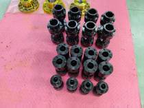
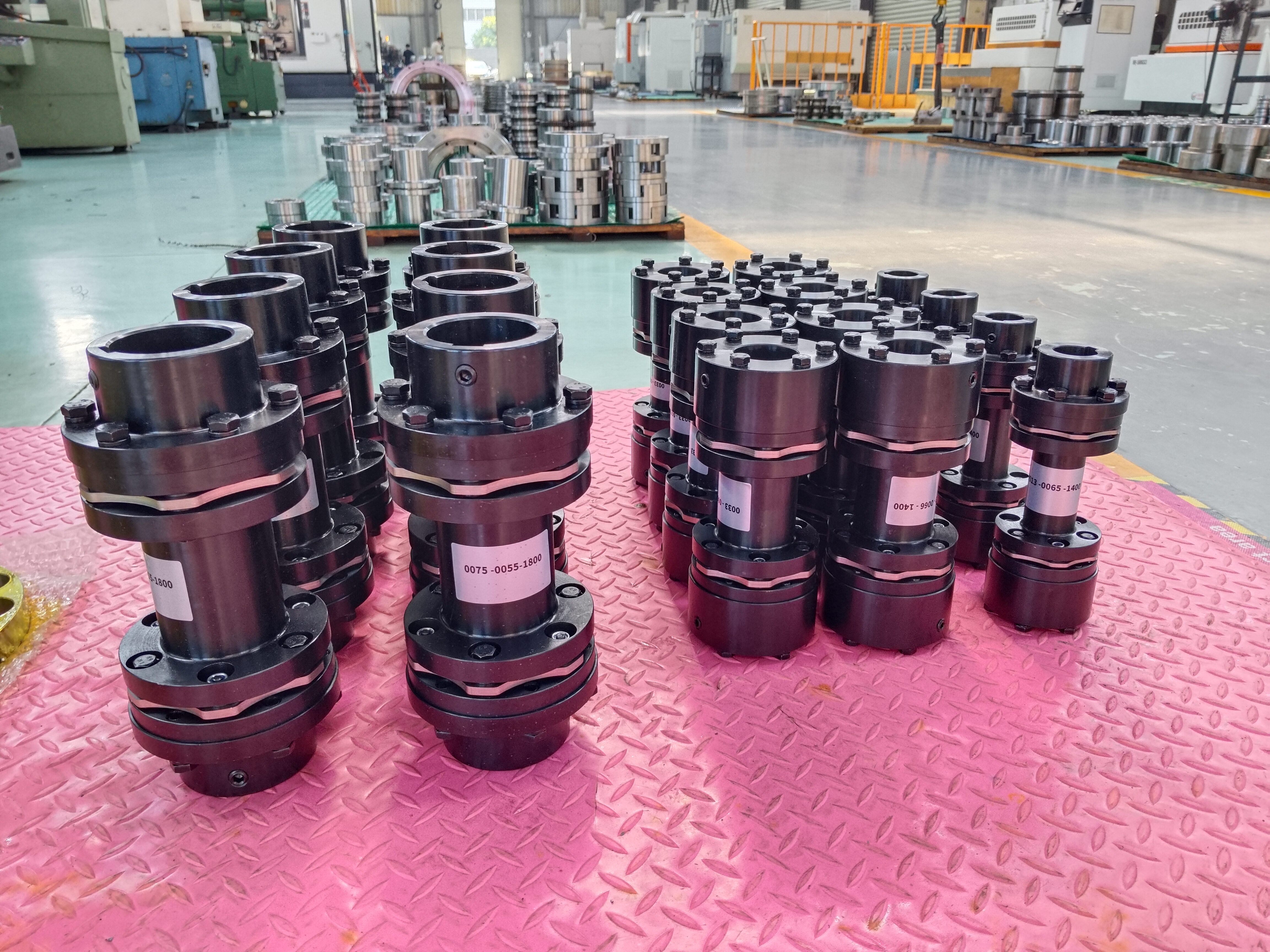
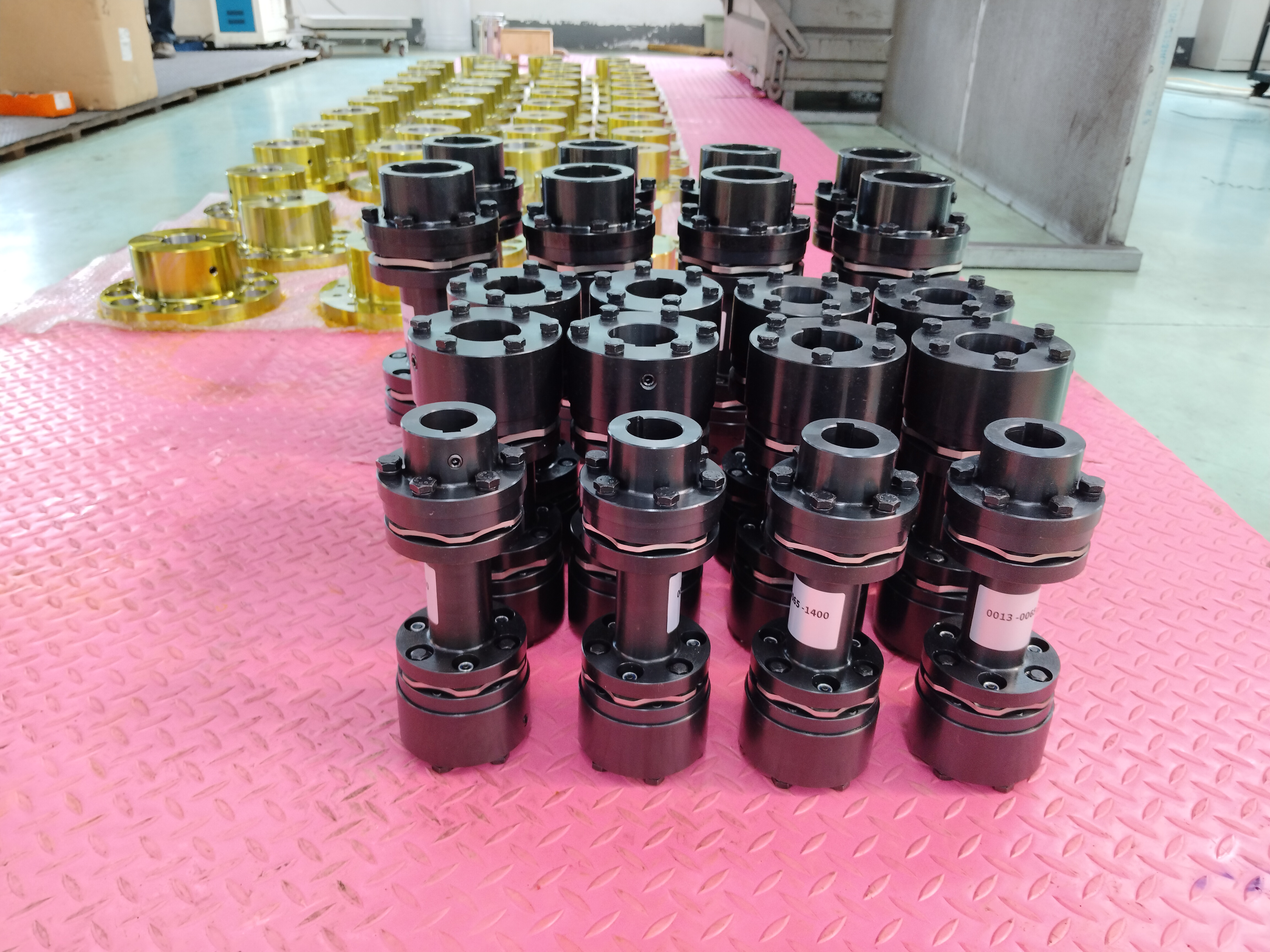
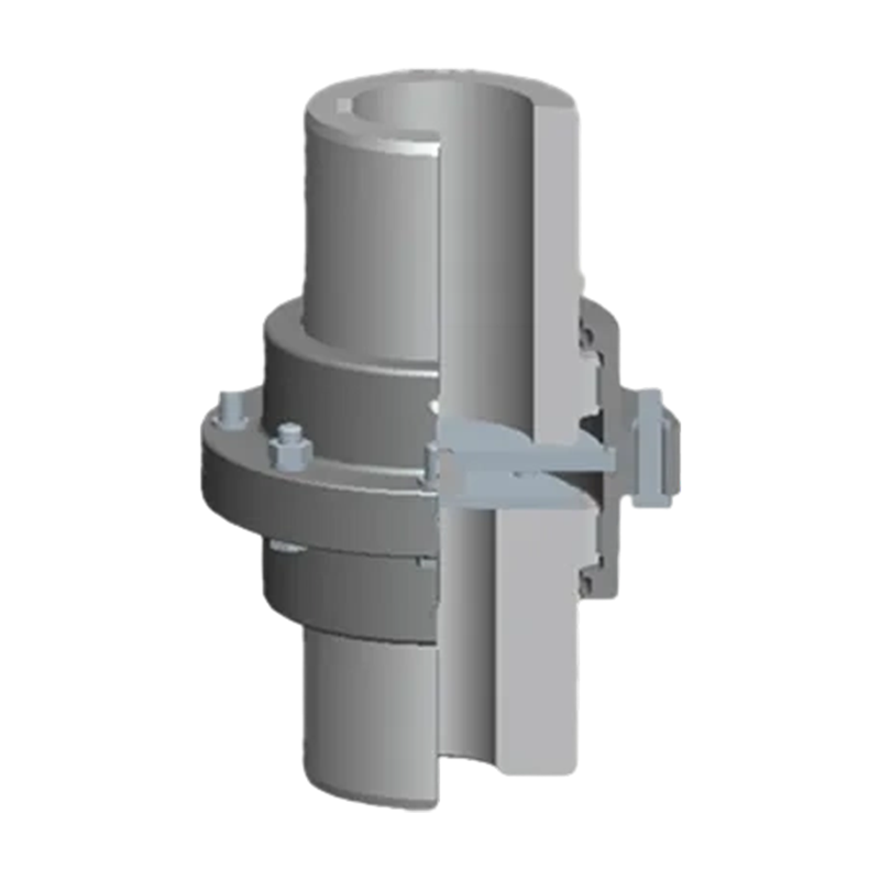
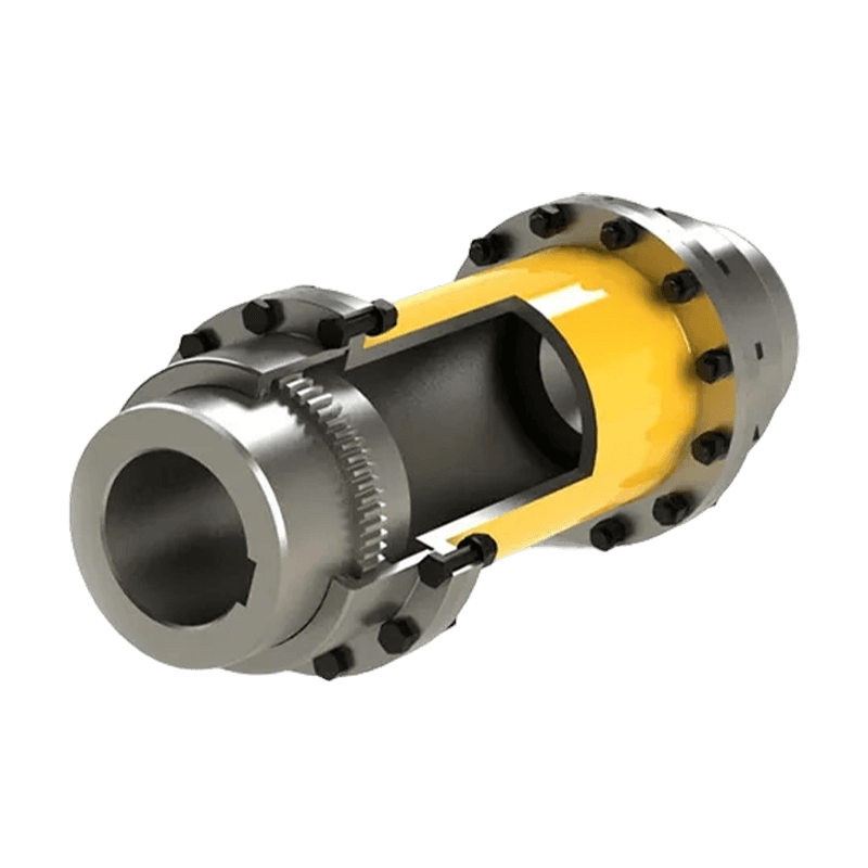
Among diaphragm coupling variants used in industrial drive systems, the MPJ type diaphragm coupling with intermediate shaft, built to the Q/YP 21002X-2018 specification, addresses a specific engineering need: transmitting torque across a longer distance between two pieces of equipment that cannot be positioned close together. Rather than connecting two diaphragm assemblies directly hub to hub, this design inserts a high-strength intermediate shaft between two diaphragm units, one mounted near the driving equipment and one near the driven equipment. This arrangement allows the coupling to span a considerable installation gap while still correcting for diagonal, axial, and parallel displacement that develops across that span due to foundation variance or thermal shaft growth.
Compared with snake spring couplings, which use a coiled metal spring element wound through grooved hub teeth to transmit torque and absorb some shock, the MPJ diaphragm design relies on an all-metal diaphragm assembly rather than a spring-and-groove mechanism. This structural difference contributes to a notably rigid torsional response and favorable dynamic balancing behavior, since there is no loose spring element subject to shifting under centrifugal force at higher rotational speeds. The result is stable torque transmission even as shaft speed increases, along with reduced mechanical stress transferred into bearings and housings, and a lower tendency toward vibration during continuous operation.
What Role Does the Intermediate Shaft Play in Long-Distance Power Transmission?
The intermediate shaft functions as a rigid connecting member between the two diaphragm assemblies, and its length is selected according to the physical distance between the driving and driven equipment within the drive system. In applications such as conveyor drive systems at ore processing sites or pump arrangements where the motor sits some distance from the driven unit due to layout or safety clearance requirements, this shaft allows torque to travel across that gap without requiring the motor and pump to sit directly adjacent to one another. Because the shaft itself is manufactured from high-strength alloy steel and sized to resist bending under torque load, it maintains straightness across its span, which in turn helps the diaphragm assemblies at each end perform their misalignment compensation function as intended rather than compensating for a bent or undersized shaft.
Why Does Diagonal, Axial, and Parallel Displacement Matter in Large-Span Installations?
Over a long installation span, small variations in foundation settling, thermal expansion of the shaft under operating temperature, or minor errors during initial alignment can accumulate into displacement that would be difficult for a short, direct coupling to absorb. The diaphragm assemblies positioned at either end of the intermediate shaft each flex independently to correct for the specific type of displacement occurring at their respective connection point, whether that displacement is angular, axial, or a combination of both. This distributed compensation approach is part of why the design suits large-span installations where a single coupling point would otherwise be under excessive bending stress.
What Materials and Manufacturing Steps Are Involved in Producing These Couplings?
The diaphragm discs are generally produced from stainless steel or heat-treated alloy steel, materials selected for their ability to flex repeatedly through many operating cycles without developing fatigue cracks. Manufacturing typically involves precision stamping or laser cutting to form the diaphragm profile, followed by a controlled heat treatment process that sets the mechanical properties needed for long-term flexing performance. Hub components and the intermediate shaft are machined from carbon steel or alloy steel and bored to shaft diameter with tight tolerances, since even minor bore inaccuracy can introduce vibration once the assembly is rotating at operating speed within an industrial drive system.
Bolted connections between the diaphragm and adjoining hubs are torqued to specified values during assembly, since uneven bolt loading can distort the diaphragm's flexing profile and shorten its service life.
In installations exposed to moisture or airborne dust, such as those near crushing and screening equipment at quarry operations, corrosion-resistant coatings or stainless steel construction for exposed hub surfaces help extend the interval between inspections.
What Performance Characteristics Should Be Expected from This Coupling Type?
Because the diaphragm assembly transmits torque through continuous metal-to-metal contact rather than sliding or meshing surfaces, backlash remains close to zero throughout the coupling's service life. Torsional rigidity is comparatively high, meaning the coupling twists very little under load, which supports applications where rotational timing between connected shafts needs to stay consistent, such as generator drive shafts in power stations or precision metering pump drives. Dynamic balancing performance also tends to be favorable, since the all-metal construction avoids the mass distribution irregularities that can occur with spring-based or elastomeric designs at higher rotational speeds.
| Characteristic | MPJ Diaphragm Coupling | Snake Spring Coupling |
|---|---|---|
| Torque transmission element | Flexing metal diaphragm | Coiled spring within grooved hubs |
| Torsional rigidity | Comparatively high | Moderate, with some flexibility |
| Maintenance need | Low, no lubrication required | Periodic lubrication of spring groove |
| Suited installation span | Long distance, with intermediate shaft | Shorter shaft spacing |
Where Are These Couplings Applied Within Ghana's Industrial Drive Systems?
Ghana's mining sector, including gold and manganese operations, often involves conveyor and crusher drive arrangements where motor placement is dictated by structural layout rather than proximity to the driven equipment, making intermediate shaft coupling designs a practical fit for connecting these spaced-apart components within a larger drive system. Cement manufacturing facilities apply similar long-span coupling arrangements within kiln drive trains, where thermal expansion along the shaft length during continuous firing cycles requires the diaphragm assemblies to correct for displacement that develops gradually during operation.
Power generation facilities, including thermal and hydroelectric plants, use diaphragm couplings with intermediate shafts to connect turbines to generators positioned at a fixed distance apart within the powerhouse layout. Water treatment and irrigation pumping installations also apply this coupling type where pump and motor placement is separated by structural or maintenance access requirements, allowing torque to travel across the gap while the diaphragm sections handle any resulting misalignment at each connection point.
What Should Be Reviewed Before Selecting and Installing This Coupling Type?
Selection begins with confirming the torque and rotational speed requirements of the connected equipment against the coupling's rated capacity, along with measuring the actual installation span so the intermediate shaft length can be specified correctly for the drive system in question. Shaft bore diameter and keyway dimensions on both the driving and driven sides need to match the coupling hubs precisely, since a poorly fitted connection can introduce vibration regardless of how well the diaphragm assembly itself is rated for the application.
During installation, technicians typically use laser alignment tools to set the initial position of both diaphragm assemblies relative to the connected equipment before securing bolted connections to the torque values specified by the manufacturer.
Following installation, periodic inspection of the diaphragm sections for fatigue cracking is advisable, particularly in continuous-duty settings such as kiln drives or generator shafts where the coupling operates for extended periods without interruption. Where the installation is exposed to dust or moisture, protective guarding around the diaphragm sections and intermediate shaft helps limit contamination that could otherwise affect balancing performance over time within Ghana's industrial drive systems.
- Quick Links
- About
- Products
- Our Service
- News & Events
- Contact
- Products Series
- Flexible Couplings with Non-Elastic Elements
- Flexible Couplings with Metal Elastic Elements
- Flexible Couplings with Non-Metallic Elastic Elements
- Safety Coupling
- Rigid Coupling
- Contact Us
- Tel : +86 511 8572 3800 +86 511 8572 3900
- Mobile : +86 15106109009
- Email : sales@couplingzy.com
- Add:No.1 Zhongye Yingbin Avenue, Gaozi Street, Dantu Economic Development Zone, Zhenjiang City, Jiangsu Province, China.


