:+86 15106109009
:sales@couplingzy.com


 English
  русский
  Español
  عربى
عربى  Português
  Deutsch
  Türk
Türk  Indonesia

What Is a Coupling Shaft Motor?
Content
- 1 What Is a Coupling Shaft Motor?
- 2 Types of Shaft Couplings Used with Motors
- 3 Shaft Misalignment: The Root Challenge
- 4 Coupling Type Comparison at a Glance
- 5 Key Benefits of Proper Coupling Selection
- 6 How to Select the Right Coupling for Your Motor
- 7 Installation and Alignment Best Practices
- 8 Maintenance and Condition Monitoring
- 9 Frequently Asked Questions
- 9.1 What is the difference between a rigid and a flexible coupling for a motor shaft?
- 9.2 How do I know if my coupling is failing?
- 9.3 Can I use any coupling size as long as the bores fit?
- 9.4 What is a service factor in coupling selection?
- 9.5 Is direct coupling always better than belt or chain drive for a motor?
What Is a Coupling Shaft Motor?
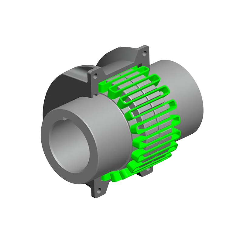
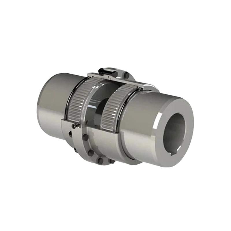
A coupling shaft motor refers to a motor-driven system in which a mechanical coupling connects the motor's output shaft to a driven component — such as a pump, compressor, gearbox, conveyor, or fan. The coupling serves as the critical mechanical bridge between the rotating motor shaft and the load shaft, transferring rotational energy (torque) while accommodating slight positional discrepancies between the two shafts.
In essence, "coupling" in this context means the method by which two rotating shafts are joined. The coupling shaft motor assembly exists in virtually every industrial environment: manufacturing lines, HVAC systems, water treatment facilities, oil refineries, food processing plants, and power generation stations all rely on these mechanisms to function reliably.
Core Components of the Assembly
A typical coupling shaft motor assembly includes several key elements working in concert:
- Motor shaft: The output shaft extending from the motor housing, rotating at a defined speed and delivering torque.
- Coupling body: The mechanical device joining both shafts — rigid or flexible, depending on the application.
- Driven shaft: The input shaft of the connected load device (pump, gearbox, etc.).
- Keyways and set screws: Secondary fastening elements that prevent shaft slippage under high torque conditions.
- Coupling guard: A safety enclosure that covers the rotating coupling to protect personnel and nearby equipment.
Types of Shaft Couplings Used with Motors
The selection of coupling type significantly impacts system performance, maintenance intervals, and vibration characteristics. Below are the major categories of couplings encountered in motor-driven applications.
Rigid Couplings
Designed for perfectly aligned shafts, rigid couplings offer zero flex and maximum torque transmission, but require precise shaft alignment during installation. They are most commonly found in precision machine tools and applications where shaft positions are fixed by design.
Flexible (Elastomeric) Couplings
These feature a rubber or polyurethane element between hubs that absorbs vibration, dampens shock loads, and accommodates angular and parallel misalignment. They are highly versatile and widely used across general industrial motor applications.
Jaw Couplings
Two metal hubs with interlocking "jaws" and a spider insert between them. Jaw couplings are excellent for general-purpose motor drives, offering a good balance of flexibility, torque capacity, and cost-effectiveness.
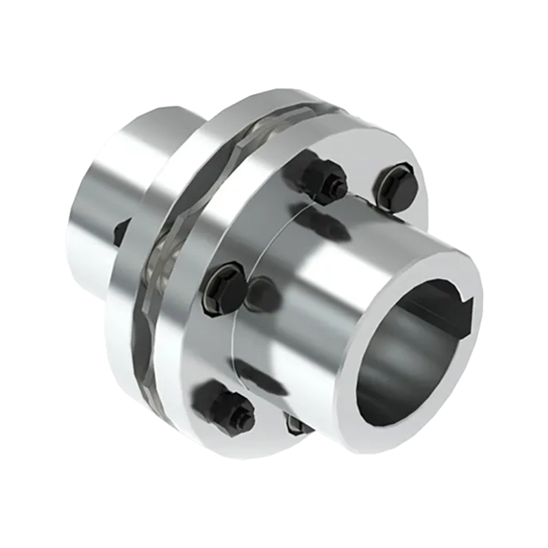
Disc Couplings
Using thin metallic disc packs to transmit torque, disc couplings flex to accommodate misalignment while remaining torsionally stiff and backlash-free — making them ideal for servo motor and precision drive applications.
Chain Couplings
These use a double-strand roller chain connecting two sprocket hubs. Suitable for higher-torque, lower-speed applications, chain couplings are easy to disassemble and inspect without moving connected equipment.
Magnetic Couplings
Transfer torque through magnetic fields without physical contact. Used in sealed, hermetic systems where fluid containment is critical, such as chemical pumps and pharmaceutical processing equipment.
Shaft Misalignment: The Root Challenge
One of the primary reasons shaft couplings exist is to manage shaft misalignment — the condition in which a motor's output shaft and a driven machine's shaft are not in perfect coaxial alignment. Misalignment can arise due to thermal expansion during operation, foundation settling, vibration-induced movement, or manufacturing tolerances. There are three fundamental types that a coupling shaft motor system must contend with.
Angular Misalignment
The shaft centerlines intersect at an angle rather than being parallel. This creates cyclical bending stress in rigid connections. Flexible couplings accommodate this by deflecting their elastic or metallic elements through each rotation.
Parallel (Offset) Misalignment
The shaft centerlines run parallel but are laterally offset. This is the most damaging form of misalignment for bearings and seals. Flexible couplings absorb this offset, preventing destructive radial forces from transmitting into motor and driven-equipment bearings.
Axial Misalignment
The two shafts are in line but exhibit end-play or thrust movement along the axis. Certain flexible coupling designs — such as disc and elastomeric types — can accommodate controlled axial movement while maintaining torque transmission.
Even "flexible" couplings are designed to minimize misalignment, not compensate for it indefinitely. Always perform precision alignment using laser or dial-indicator methods during installation. Coupling flexibility is a safety margin, not a substitute for good alignment practice.
Coupling Type Comparison at a Glance
Selecting the right coupling involves balancing torque requirements, misalignment tolerance, operating speed, and maintenance access. The following outlines the key characteristics of the most common coupling types used in motor shaft applications.
- Rigid: Very low misalignment tolerance, no shock absorption, zero backlash. Best for precision machine tools.
- Jaw / Spider: Moderate misalignment tolerance, good shock absorption, low backlash. Ideal for general industrial motors.
- Disc: Moderate misalignment tolerance, minimal shock absorption, zero backlash. Best suited for servo motors and encoders.
- Elastomeric: High misalignment tolerance, excellent shock absorption, some backlash. Widely used for pumps, fans, and compressors.
- Chain: Moderate misalignment tolerance, moderate shock absorption, moderate backlash. Common in heavy-duty conveyor systems.
- Magnetic: High misalignment tolerance, inherent shock isolation, zero backlash. Required for sealed and hermetic pump applications.
Key Benefits of Proper Coupling Selection
Choosing and installing the correct coupling for a motor shaft application delivers measurable advantages across the entire system lifecycle.
Extended Equipment Life
A correctly selected coupling reduces the radial and axial loads imposed on motor bearings and driven-machine bearings. Bearing failure is the leading cause of motor downtime; effective coupling selection directly extends bearing service life, sometimes by a factor of two or three.
Vibration and Noise Reduction
Elastomeric and flexible couplings act as torsional dampers, absorbing pulsations from reciprocating machinery before they can excite resonance in the motor shaft or support structure. This reduces noise levels and structural fatigue over time.
Overload Protection
Many coupling designs — particularly those with elastomeric or shear-pin elements — provide a degree of mechanical fuse behavior. When torque spikes exceed a threshold, the coupling absorbs or releases the energy rather than transmitting destructive forces to the motor or driven equipment.
Simplified Maintenance
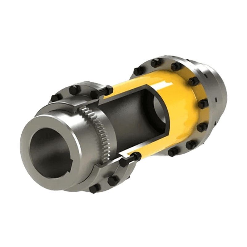
Certain coupling designs — such as split-hub or spacer-type couplings — allow the coupling element to be replaced without moving the motor or driven machine. This dramatically reduces maintenance time and associated labor costs.
How to Select the Right Coupling for Your Motor
Coupling selection is an engineering decision that should be based on the specific demands of the application. Follow this structured process to arrive at the optimal choice.
- Determine Torque Requirements. Calculate the full-load torque from the motor specifications, then apply a service factor based on driven load type (smooth, moderate shock, heavy shock). The coupling's rated torque must exceed this design torque.
- Identify Shaft Sizes and Bore Requirements. Measure the motor output shaft diameter and the driven shaft diameter. These dimensions determine the coupling hub bore size required, and whether a reducer bushing is necessary to match different shaft diameters.
- Assess Misalignment Conditions. Evaluate whether the installation will involve angular, parallel, or axial misalignment — and to what degree. High misalignment tolerance requirements favor flexible couplings; precision servo systems favor zero-backlash disc or bellows designs.
- Consider Operating Speed (RPM). All couplings have a maximum speed rating. Motors operating above 3,000 RPM require dynamically balanced couplings to prevent resonance and vibration at operating speeds.
- Account for Environmental Conditions. Exposures to extreme temperature, moisture, chemicals, or explosive atmospheres influence material choices. Elastomeric elements may degrade in ozone or certain solvents; stainless steel or ATEX-rated designs may be required.
- Verify Space Envelope and Axial Clearance. Confirm that the chosen coupling fits within the available space between the motor and driven machine, including adequate axial clearance for thermal growth and shaft end-float.
Installation and Alignment Best Practices
Even the highest-quality coupling will underperform or fail prematurely if installed incorrectly. Proper installation of a coupling shaft motor begins before a single fastener is tightened.
Shaft Preparation
Clean all shaft surfaces and bores of rust, burrs, and contamination. Check shaft diameter tolerances with a micrometer to verify they fall within the coupling's bore tolerance range. Apply a light film of anti-seize to interference-fit surfaces where appropriate.
Hub Installation
Coupling hubs should be fitted to the motor and driven machine shafts before aligning the machines. For interference-fit hubs, use a hub puller and a press or induction heater. Never hammer hubs onto shafts, as this damages bearings and internal components.
Precision Shaft Alignment
After mounting hubs, align the two machines using laser alignment tools or dial indicator setups. Modern precision alignment targets for flexible couplings are typically 0.05 mm (0.002 in.) or better for parallel offset and 0.05°–0.1° for angular misalignment. Record initial alignment readings as a baseline for future predictive maintenance comparisons.
Torque Fasteners to Specification
Always use a calibrated torque wrench to tighten coupling fasteners to manufacturer-specified values. Under-torqued fasteners loosen under vibration; over-torqued fasteners stretch or damage coupling components.
Maintenance and Condition Monitoring
Coupling shaft motor systems benefit enormously from proactive maintenance strategies. Unlike rolling element bearings — which often fail suddenly — most coupling wear modes develop progressively and can be detected early.
Common Signs of Coupling Wear or Failure
- Increased vibration levels at the motor or driven machine bearings.
- Rhythmic clicking, squealing, or rattling sounds from the coupling area.
- Elevated bearing temperatures near the coupling end of the motor.
- Visible rubber or polyurethane debris (spider element fragments) near jaw couplings.
- Progressive shaft misalignment detected during periodic laser alignment checks.
Recommended Maintenance Intervals
For most industrial coupling shaft motor assemblies, perform a visual inspection every three months. Conduct a precision alignment check and coupling torque verification annually or following any significant process change, thermal event, or detected vibration increase. Replace elastomeric elements on schedule — typically every 2–5 years depending on operating duty — rather than waiting for failure.
Frequently Asked Questions
What is the difference between a rigid and a flexible coupling for a motor shaft?
A rigid coupling connects two shafts without any flexibility, transmitting torque with maximum efficiency but requiring near-perfect shaft alignment. A flexible coupling incorporates an elastic or metallic element that allows it to flex during each revolution, accommodating misalignment, dampening vibration, and protecting motor and driven-machine bearings from excess radial loading.
How do I know if my coupling is failing?
The most reliable indicators include elevated vibration readings (particularly at 1× and 2× running speed), unusual noise from the drive area, rubber or polymer debris near jaw or elastomeric couplings, and rising bearing temperatures on the motor or driven machine. Periodic laser alignment checks will also reveal if the machines have shifted, which can indicate coupling or baseplate issues.
Can I use any coupling size as long as the bores fit?
No. The bore sizes of the coupling hubs must match the shaft diameters, but the coupling must also be rated for the system's torque, speed (RPM), misalignment conditions, and service factor. Using an undersized coupling — even with correctly fitting bores — will result in premature failure, potentially violent, during operation.
What is a service factor in coupling selection?
A service factor is a multiplier applied to the calculated load torque to account for real-world conditions such as starting torque surges, shock loads, reversing operation, and duty cycle variations. For smooth loads like centrifugal pumps, a service factor of 1.0–1.25 is typical. For heavy shock loads such as crushers or presses, service factors of 2.0 or higher may be required.
Is direct coupling always better than belt or chain drive for a motor?
Direct coupling offers the highest mechanical efficiency at 98–99% and simplest maintenance, but it requires precise speed matching between the motor and driven machine. Belt and chain drives add the flexibility to change speed ratios and provide some inherent shock isolation. The best choice depends on the speed ratio needed, available space, alignment precision achievable, and the acceptable efficiency loss for the application.
- Quick Links
- About
- Products
- Our Service
- News & Events
- Contact
- Products Series
- Flexible Couplings with Non-Elastic Elements
- Flexible Couplings with Metal Elastic Elements
- Flexible Couplings with Non-Metallic Elastic Elements
- Safety Coupling
- Rigid Coupling
- Contact Us
- Tel : +86 511 8572 3800 +86 511 8572 3900
- Mobile : +86 15106109009
- Email : sales@couplingzy.com
- Add:No.1 Zhongye Yingbin Avenue, Gaozi Street, Dantu Economic Development Zone, Zhenjiang City, Jiangsu Province, China.


