:+86 15106109009
:sales@couplingzy.com


 English
  русский
  Español
  عربى
عربى  Português
  Deutsch
  Türk
Türk  Indonesia

What is the role of shaft couplings in heavy equipment?
Content
- 1 Understanding the Role of Shaft Couplings in Heavy Equipment
- 2 Step 1 — Determine the Nominal Transmitted Torque
- 3 Step 2 — Apply Service Factors to Determine Design Torque
- 4 Step 3 — Identify Peak and Shock Torque Conditions
- 5 Step 4 — Quantify Shaft Misalignment
- 6 Step 5 — Torsional Vibration Analysis for Heavy Equipment Drives
- 7 Step 6 — Select the Coupling Size from Catalogue
- 8 Step 7 — Verify Bore and Keyway Capacity
- 9 Step 8 — Mass Moment of Inertia and Starting Load Verification
- 10 Practical Sizing Example: Conveyor Drive Coupling
- 11 Common Sizing Mistakes in Heavy Equipment Applications
- 12 Pre-Installation and Commissioning Checklist
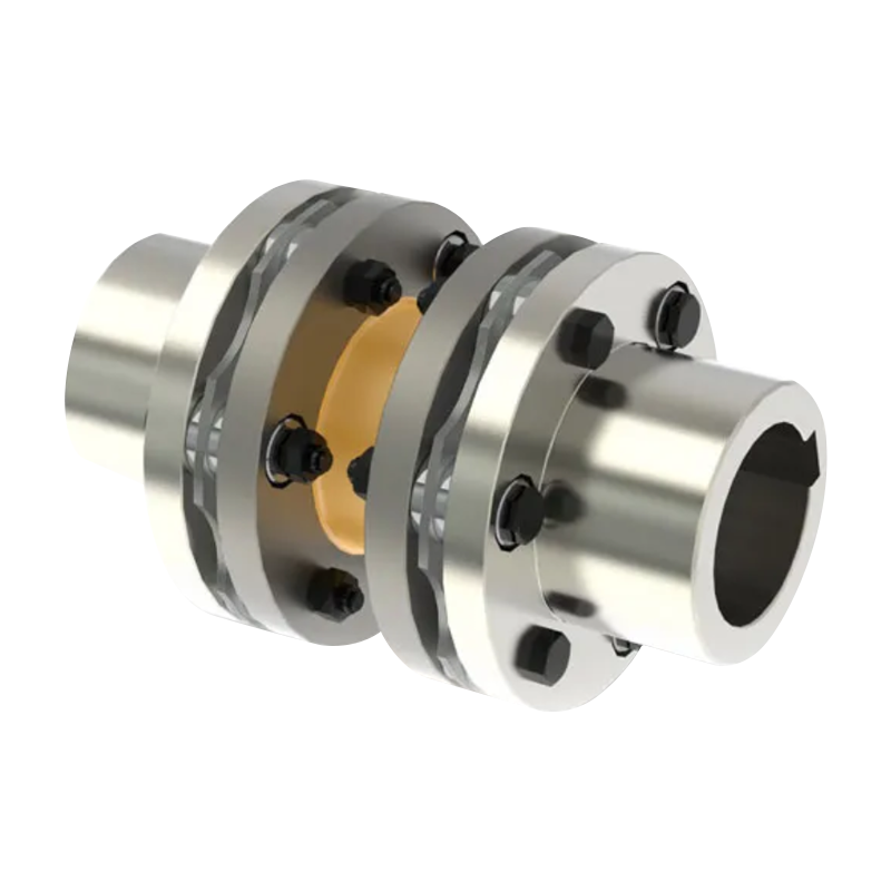
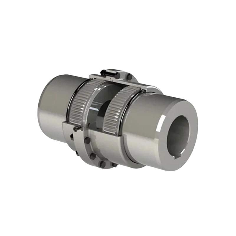
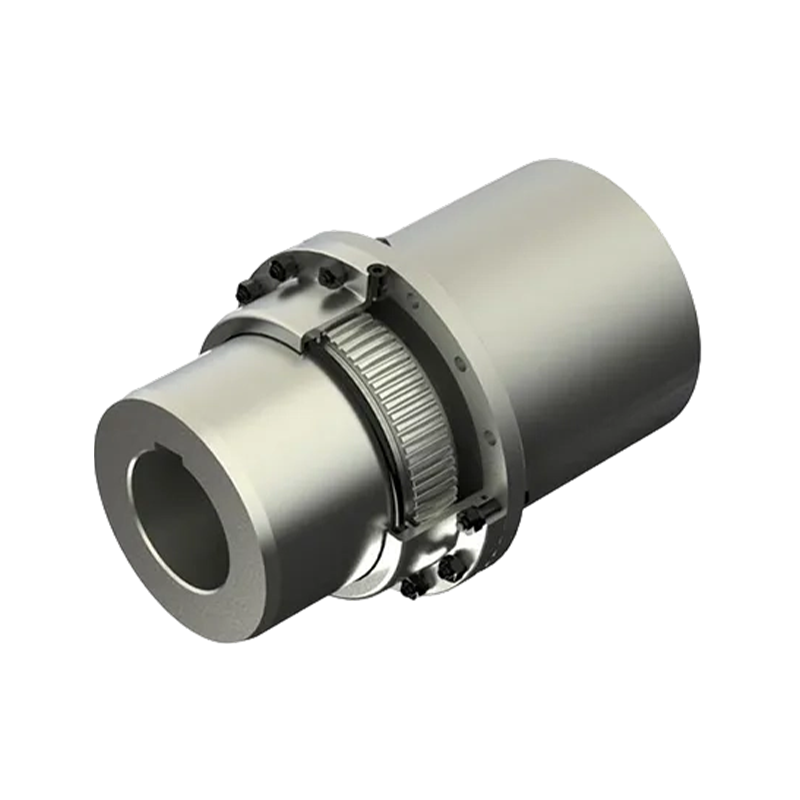
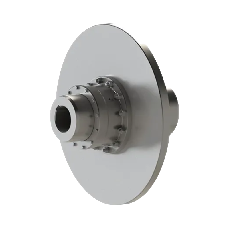
In heavy equipment — crushers, mills, pumps, compressors, conveyors, and industrial drives — a shaft coupling is the mechanical link between the power source and the driven load. Selecting and sizing the wrong coupling is one of the most reliable ways to cause unexpected downtime: couplings that are too small fail under peak torque, those that are too large add unnecessary mass and inertia, and those chosen without regard for misalignment or shock conditions deteriorate rapidly. This guide covers the complete sizing process, from torque calculations through service factors, misalignment capacity, torsional analysis, and final selection criteria.
Understanding the Role of Shaft Couplings in Heavy Equipment
A shaft coupling connects two rotating shafts — typically a driver (motor, engine, or gearbox output) and a driven machine — to transmit torque and rotational speed. In heavy equipment, couplings must do this under conditions that would destroy a poorly specified component: high continuous torque, frequent shock loads from crusher jaws or compressor pistons, thermal cycling, shaft misalignment caused by foundation settlement or thermal growth, and decades of continuous duty.
Beyond simple torque transmission, couplings in heavy industrial settings serve several additional functions:
- Misalignment accommodation: compensating for angular, parallel, and axial shaft misalignment that cannot be entirely eliminated during installation or that develops in service
- Vibration damping: attenuating torsional vibration spikes that would otherwise propagate into gearboxes, motors, and driven equipment
- Overload protection: acting as a mechanical fuse that fails preferentially to protect more expensive downstream components
- Electrical isolation: preventing stray currents from travelling shaft-to-shaft in certain industrial environments
Step 1 — Determine the Nominal Transmitted Torque
Every sizing calculation begins with the nominal torque being transmitted. If the driver power and speed are known, nominal torque is calculated directly:
P = transmitted power (kW)
n = shaft speed (RPM)
9550 = unit conversion constant (converts kW and RPM to N·m)
Alternative in imperial units: Tn (lb·in) = (P (HP) × 63,025) / n (RPM)
In heavy equipment, "nominal" torque is the average steady-state torque under full design load. This is not the peak torque the coupling must survive — that figure is derived in the next step using service factors. Always confirm whether the power figure used is motor nameplate power, shaft output power after gearbox efficiency losses, or the actual demand of the driven machine at its design operating point.
Step 2 — Apply Service Factors to Determine Design Torque
Nominal torque is the baseline. The design torque — the value used for coupling selection — accounts for peak loads, shock events, start-up torque, and application severity. This is done by multiplying the nominal torque by a composite service factor:
Tn = nominal transmitted torque (N·m)
fs = composite service factor (dimensionless) — product of all applicable sub-factors
The composite service factor is built from several components, each addressing a different source of loading beyond steady-state nominal torque:
| Sub-factor | Description | Typical range for heavy equipment |
|---|---|---|
| fA — Application / load type | Accounts for nature of the driven load: smooth, moderate shock, heavy shock | 1.0 (smooth) to 3.0 (heavy impact, e.g. jaw crusher) |
| fS — Start-up / peak torque | Electric motors produce 2–4× nameplate torque during direct-on-line starting | 1.5–3.5 for direct-on-line; 1.0–1.5 for VFD or soft-start |
| fT — Temperature | Reduces rated torque of elastomeric elements at elevated operating temperatures | 1.0 at ≤50°C; up to 1.5 at 80–100°C operating environments |
| fH — Hours per day / duty cycle | Continuous 24-hour operation demands higher derating than 8-hour shifts | 1.0 (≤8 hr/day) to 1.25 (24 hr/day continuous) |
| fM — Misalignment severity | Higher misalignment imposes additional bending loads on coupling elements | Applied as reduction of allowable torque — check per manufacturer |
Step 3 — Identify Peak and Shock Torque Conditions
In heavy equipment, the distinction between design torque and peak torque is critical. Design torque — nominal torque multiplied by service factors — governs the selection for continuous operation and fatigue life. But the coupling must also withstand occasional peak events without plastic deformation or fracture.
Common peak torque events in heavy equipment include:
- Stall torque during motor start-up: for direct-on-line starts, locked-rotor torque can reach 6–8× rated torque in large squirrel cage motors. The coupling sees this load every time the machine is started.
- Crusher or shredder jam and release: when a jaw crusher jams on uncrushable material and then releases suddenly, the stored elastic energy in the driveline discharges as a torque spike that can be 3–5× running torque.
- Compressor backpressure surges: reciprocating compressors generate significant torque fluctuations at each cylinder firing event — the amplitude depends on the number of cylinders and speed.
- Conveyor belt slip and catch: a loaded belt that slips on the drive pulley and then grips generates an impulsive torque.
The coupling's maximum peak torque rating (Tmax or TKS in many catalogues) must exceed all identified peak events with an adequate safety margin. For heavy industrial equipment, a minimum ratio of TKS/Tdesign of 1.5–2.0 is recommended. For crushers and similar high-shock machines, 2.0–3.0 is more appropriate.
Step 4 — Quantify Shaft Misalignment
Perfect shaft alignment does not exist in heavy equipment in service. Foundation settlement, thermal growth of hot equipment, bearing wear, and assembly tolerances all produce misalignment that the coupling must tolerate without generating excessive bending loads, vibration, or premature wear of its flexible elements.
Three types of misalignment must be individually quantified and compared against the coupling's rated capacity:
The angle between the two shaft centrelines, measured in degrees or milliradians. Most common type in heavy equipment due to differential thermal growth and foundation tilt.
Lateral offset between shaft centrelines, measured in mm. Caused by alignment error, bearing wear, or structural deflection. Most damaging to coupling elements.
Axial displacement between shaft ends, caused by thermal expansion, thrust loads, or end play in bearings. Must stay within coupling's axial travel range.
When multiple misalignment types are present simultaneously — which is almost always the case in real installations — they interact and reduce the allowable capacity of each type. Most manufacturer sizing methods use a combined misalignment factor or require that each component stay within a reduced fraction of its maximum rated value when the others are non-zero. The commonly applied rule of thumb is:
Δr = actual parallel offset; Δrmax = rated maximum parallel offset
Δa = actual axial displacement; Δamax = rated maximum axial displacement
If the sum exceeds 1.0, the coupling is operating beyond its misalignment envelope.
Step 5 — Torsional Vibration Analysis for Heavy Equipment Drives
Every rotating driveline has natural torsional frequencies determined by the distribution of inertias and the torsional stiffness values of the shafts, couplings, and other elements in the system. If an excitation frequency — from motor torque ripple, gear mesh, reciprocating compressor firing, or variable speed drive harmonics — coincides with a natural frequency, torsional resonance occurs. The resulting torque amplification can be many times the nominal value, causing rapid fatigue failure of couplings, keyways, and shafts.
For heavy equipment with variable speed drives, reciprocating machinery, or where startup sweeps through a wide speed range, a full torsional analysis is mandatory before finalising coupling selection. The key parameters needed are:
- Mass moment of inertia (J) of all rotating components — motor rotor, coupling hubs, gearbox elements, driven machine rotor — in kg·m²
- Torsional stiffness (CT) of each shaft segment and coupling element in N·m/rad
- Excitation frequencies — fundamental and harmonics from all periodic torque sources in the system
- Damping characteristics of the coupling's flexible element — critical for limiting resonance amplitude
CT = torsional stiffness of coupling (N·m/rad)
J1 = moment of inertia of driver-side mass (kg·m²)
J2 = moment of inertia of driven-side mass (kg·m²)
This simplified formula applies to a two-body lumped model. Real systems require multi-body modelling with specialist software.
The coupling's torsional stiffness is a key design variable in this analysis. Soft elastomeric couplings have low CT, which shifts natural frequencies downward — potentially away from operating speed excitations but potentially into the start-up speed range. Stiff metallic disc or gear couplings have high CT, placing natural frequencies well above operating speed. Neither is universally correct — the outcome depends on the specific system and excitation spectrum.
Step 6 — Select the Coupling Size from Catalogue
With design torque, peak torque, misalignment envelope, bore sizes, and torsional stiffness requirements defined, you can now select a specific coupling size from a manufacturer's programme. The minimum requirements for acceptance are:
| Parameter | Requirement | Notes |
|---|---|---|
| Rated continuous torque TKN | TKN ≥ Tdesign | The catalogue continuous torque rating must meet or exceed the calculated design torque |
| Peak torque TKS | TKS ≥ Tpeak × safety factor | With safety factor 1.5–3.0 depending on shock severity |
| Bore capacity | Maximum bore ≥ shaft diameter | Check both driver and driven shaft bores — they may differ |
| Misalignment ratings | All three misalignment types within rated capacity | Combined misalignment check per Step 4 must satisfy ≤ 1.0 |
| Maximum speed | nmax,coupling ≥ operating speed | Critical for flexible element centrifugal stress and balance |
| Torsional stiffness CT | Compatible with torsional analysis result | Must not place natural frequency within operating speed range |
Step 7 — Verify Bore and Keyway Capacity
The hub bore and keyway must transmit the full design torque without yielding the shaft, hub, or key. For a parallel key connection — the most common arrangement in heavy equipment — the key is sized and checked in both shear and compressive bearing stress:
Tdesign = design torque (N·mm — use consistent units)
d = shaft diameter (mm)
w = key width (mm)
leff = effective key engagement length (mm) — use the lesser of hub or shaft keyway length
τallowable = allowable shear stress for key material — typically 80–100 MPa for C45 steel key
h = key height (mm)
σc,allowable = allowable compressive stress — typically 150–200 MPa for keyway in medium carbon steel hub
Compressive failure typically governs before shear failure for standard key proportions.
For heavy shock applications — crushers, shredders, and reversing drives — consider a spline connection instead of a single parallel key. Splines distribute load over multiple teeth, dramatically reducing stress concentrations at the keyway root that are the most common initiation site for shaft fatigue cracks in heavy industrial drives.
Step 8 — Mass Moment of Inertia and Starting Load Verification
In heavy equipment with large driven-side inertia — long conveyor systems, large mills, high-inertia fans — the motor must accelerate the entire connected inertia from rest to full speed. The coupling transmits this acceleration torque throughout the starting period. The starting torque at the coupling can be far higher than the nominal running torque if the drive does not use a soft-start or variable frequency drive.
Jtotal = total reflected moment of inertia of driven system (kg·m²)
α = angular acceleration (rad/s²)
Δn = speed change from 0 to operating speed (RPM)
tacc = acceleration time (seconds)
The coupling must handle Tmotor,start − Tload,start + Tacc simultaneously during the starting transient.
For fluid couplings and couplings with soft-start features, the starting torque transmitted to the driven side is inherently limited by the coupling's design. For rigid-element couplings (gear, disc, grid), the full motor starting torque is transmitted, and the coupling must be sized to handle it.
Practical Sizing Example: Conveyor Drive Coupling
A belt conveyor is driven by a 315 kW, 1,485 RPM motor through a fluid coupling and gearbox. The coupling at the gearbox output shaft (shaft diameter 140 mm, speed 148.5 RPM after a 10:1 gearbox) must be sized. The application involves moderate shock loads (ore conveyor), 24-hour continuous operation.
- Nominal torque at coupling: Tn = (315 × 9550) / 148.5 = 20,252 N·m
- Service factors: application factor fA = 1.5 (moderate shock, ore); duty factor fH = 1.25 (24 hr/day); temperature factor fT = 1.0 (ambient service). Composite fs = 1.5 × 1.25 × 1.0 = 1.875
- Design torque: Tdesign = 20,252 × 1.875 = 37,973 N·m → round up to select coupling rated ≥ 38 kN·m
- Peak torque check: motor starting torque transmitted (fluid coupling limits this) — confirmed ≤ 2× Tn by fluid coupling characteristic. Peak torque = 2 × 20,252 = 40,504 N·m. Select coupling with TKS ≥ 60 kN·m (1.5× safety on peak)
- Bore: 140 mm shaft — confirm selected coupling size accommodates 140 mm bore with keyway per DIN 6885
- Result: a grid coupling in the 45–50 kN·m continuous rating range with 80 kN·m peak rating satisfies all criteria
Common Sizing Mistakes in Heavy Equipment Applications
- Sizing on nominal power alone without service factors. In heavy equipment, service factors routinely double or triple the nominal torque. Omitting them produces a systematically undersized coupling.
- Using motor nameplate power instead of actual shaft torque at the coupling location. After a gearbox, torque is multiplied by the gear ratio (less efficiency losses). A coupling on the output side of a 10:1 gearbox sees 10× the motor shaft torque.
- Ignoring torsional resonance in variable speed drives. VFDs sweep through a wide frequency range during acceleration. Without a torsional analysis, the system may resonate at a speed that falls within the normal operating range.
- Specifying cold-alignment misalignment as the maximum. Thermal growth of large motors, gearboxes, and process equipment can add several millimetres of offset at operating temperature. Size for the hot-running condition.
- Selecting the smallest coupling that meets the torque requirement without checking speed. Large couplings with elastomeric elements have maximum speed limits driven by centrifugal stress. At high speeds, the next larger size may be required even if torque capacity is adequate.
- Neglecting hub-to-shaft fit verification. A coupling sized correctly for torque but installed with insufficient interference fit or an undersized key will still fail — at the shaft connection, not the coupling element itself.
Pre-Installation and Commissioning Checklist
- Confirm shaft diameters match the coupling's bore specification — measure, do not assume
- Verify keyway dimensions comply with the standard referenced in the coupling data sheet (typically DIN 6885 or ANSI B17.1)
- Measure and record cold-alignment offsets before final coupling installation
- Confirm coupling element or spider condition before assembly — replace if any sign of wear or cracking
- Apply correct torque to all hub fasteners — undertorqued fasteners are the primary cause of coupling bolt failures in heavy drives
- Check coupling assembly for correct axial positioning — coupling hubs must be set at the specified gap (DBSE — distance between shaft ends) per the installation drawing
- After first full thermal cycle at operating temperature, re-check alignment and re-torque fasteners
- Establish an inspection interval for flexible coupling elements — elastomers harden and crack with age independent of load hours
Sizing shaft couplings for heavy equipment is a systematic process that goes well beyond matching a bore diameter to a shaft. Correct sizing requires calculating nominal torque from power and speed, selecting appropriate service factors for the application severity and duty cycle, identifying peak and shock torque events, quantifying the three-dimensional misalignment envelope in hot running conditions, and where variable speed or reciprocating machinery is involved, performing a torsional vibration analysis to confirm the coupling stiffness places natural frequencies away from excitation sources. Each parameter has a direct consequence on coupling life and reliability — and in heavy industrial equipment, an unplanned coupling failure rarely affects only the coupling itself.

- Quick Links
- About
- Products
- Our Service
- News & Events
- Contact
- Products Series
- Flexible Couplings with Non-Elastic Elements
- Flexible Couplings with Metal Elastic Elements
- Flexible Couplings with Non-Metallic Elastic Elements
- Safety Coupling
- Rigid Coupling
- Contact Us
- Tel : +86 511 8572 3800 +86 511 8572 3900
- Mobile : +86 15106109009
- Email : sales@couplingzy.com
- Add:No.1 Zhongye Yingbin Avenue, Gaozi Street, Dantu Economic Development Zone, Zhenjiang City, Jiangsu Province, China.


