:+86 15106109009
:sales@couplingzy.com


 English
  русский
  Español
  عربى
عربى  Português
  Deutsch
  Türk
Türk  Indonesia

What Are the Key Components of a Jaw Coupling and How Do You Select the Right One?
Content
A maintenance manager once told us that an effective way to reduce downtime on a packaging line was to stop treating the coupling as a generic replacement part. The difference was not in the torque rating alone, but in the spider durometer and the bore fit. A jaw coupling is a simple device, yet getting it right requires attention to the same parameters that drive other driveline failures: misalignment tolerance, operating temperature, and shock load.
For low to medium torque drives that run within a practical speed range, a jaw coupling offers a good balance of cost, damping, and ease of replacement. The design consists of two hubs with interlocking jaws and one replaceable elastomer spider. The good news is that many failures are preventable if you understand what the spider sees during operation.
What a Jaw Coupling Is and How It Works
A jaw coupling, also called a spider coupling, is a positive-drive flexible coupling. The two hub halves face each other with a small gap, and their jaws interleave like a gear set that does not touch. The elastomeric spider fills the free space. When the driving shaft rotates, its hub jaws press against the spider teeth, which transmit force to the driven hub.
Because the spider can deform, small amounts of angular misalignment, shaft offset, and axial movement are absorbed. The coupling also dampens vibration, which helps protect connected bearings. One important characteristic is that the spider carries the torque through its material. As the torque increases, the spider teeth compress, and this deformation allows torsional softness to absorb starting torque and reduce shock transmitted to the motor.
By design, the spider is typically the weakest component. When the system is overloaded, the spider is generally expected to fail before the metallic hubs or the shafts. This principle of a sacrificial element can significantly reduce the cost of failure, but it also means that selecting a spider with too much stiffness or too little resistance can cause repeated premature replacement.
Key Components of a Jaw Coupling
The Hubs
The two hubs are the structural part of the coupling. They are typically machined from cast iron for general applications, ductile iron for higher torque, or steel when both speed and torque are high or when the shaft sizes demand it. The jaw count varies by coupling size and is not a performance indicator on its own. Instead, the hub geometry determines how much radial space the spider has to work in and how effectively the coupling accommodates alignment differences.
The Elastomeric Spider
The spider is the element that largely defines the coupling's performance. Its material choice is a key selection decision. Polyurethane, NBR (nitrile rubber), and thermoplastic elastomer are the dominant options, and they behave differently in terms of hardness, damping, and temperature resistance.
| Material | Hardness | Operating Temperature | Damping | Key Strength |
|---|---|---|---|---|
| NBR | Shore A 70-90 | -40°C to 100°C | High | Oil and grease resistance |
| Polyurethane | Shore A 92-95 | -40°C to 80°C | Moderate | Abrasion resistance |
| Thermoplastic elastomer | Shore D 55-62 | -50°C to 135°C | Low | Chemical resistance and high temperature tolerance |
Hardness is a major factor in how the coupling behaves. A softer spider provides more damping but allows more angular deflection and runs the risk of overheating at high speed. A harder spider transmits torque with less waste but transfers more shock to the connected bearings. A suitable choice is a balance that takes the actual start-up and operating conditions into account.
Where Jaw Couplings Are Used
Jaw couplings are common in pumps, small fans, conveyors, mixers, packaging machinery, and small compressors. They tend to perform well when the driven machine does not generate heavy shock loads and the misalignment stays within the coupling's rated range. In general, the lower the angular and parallel offset, the longer the spider tends to survive.
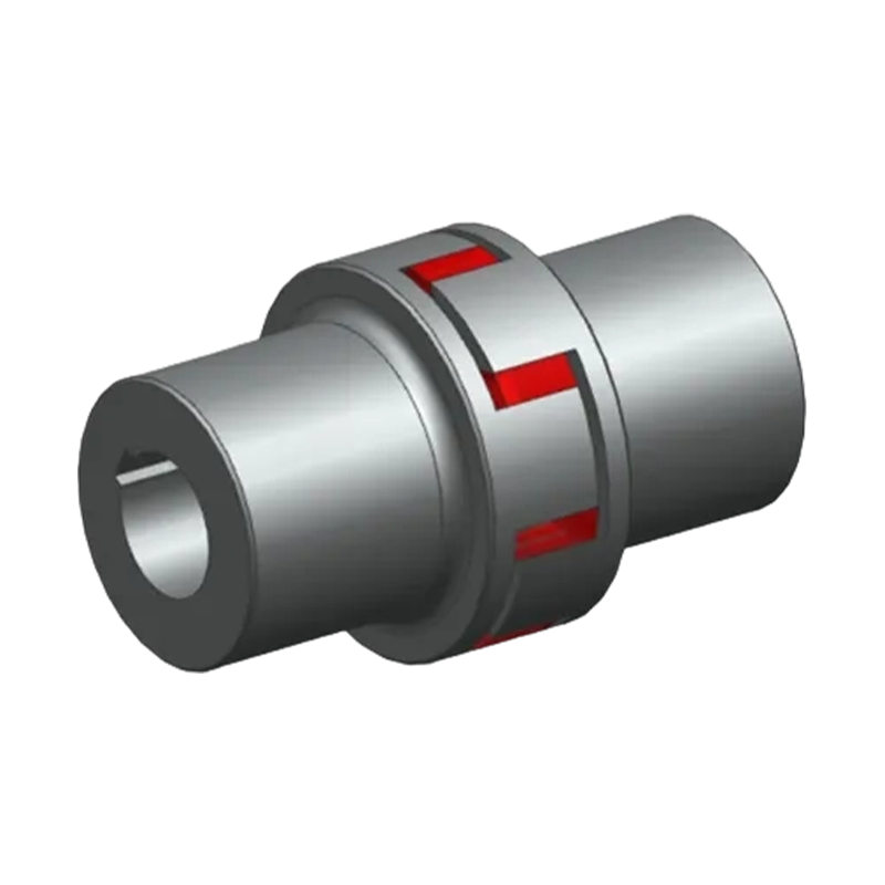 XC Type Star Elastic Coupling for Compact Shock-Absorbing DrivesThis plum-shaped elastic coupling offers a compact design with low inertia, using engineering plastic elements for cushioning and wear resistance. It operates from -35°C to 80°C and suits systems needing damping and simple axial installation.View Product →
For process equipment such as an agitator or a pump on a brewing line, the jaw coupling is often a practical choice for its simplicity and low replacement cost. A pump with a badly misaligned coupling can show wear on the spider edges within a few thousand operating hours.
Sizing and Selecting a Jaw Coupling
Start by calculating the nominal torque. The base formula is power (kW) divided by speed (RPM), multiplied by 9550. The result is the required torque under steady load. To account for starting torque, acceleration, and overload, multiply by a service factor. The service factor is usually supplied by the equipment manufacturer or the coupling manufacturer.
After torque, check the bore sizes. The shaft diameters at the driver and driven side determine the smallest suitable coupling size, because each coupling bore range has an upper and lower limit. An oversized coupling is heavier and more expensive, while an undersized coupling can cause rapid spider wear and possibly hub damage if the shaft slips.
Two more limits are easy to miss. The RPM rating for a given coupling size should be checked against the actual running speed, because the spider material can deform excessively at high speed. The angular and parallel misalignment limits should not be treated as continuous operating values. Operating at the limit can reduce service life substantially. A practical rule is to aim for a misalignment that is noticeably below the coupling's rated limit.
For a deeper look at the selection process for different drive conditions, a guide on how to select the appropriate coupling explains the key parameters in more detail.
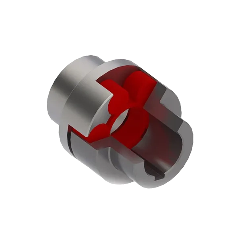 MC Plum-Shaped Elastic Coupling for Easy Maintenance and Tough DutyDesigned with a simple structure for quick disassembly, this coupling embeds elastic elements to absorb shock and protect machinery. It covers a wide torque range and is widely used in metallurgical, mining, and port equipment.View Product →
When to Use a Jaw Coupling and When Not To
Good Applications
Use a jaw coupling for machines with moderate torque, steady or gently varying loads, and required misalignment compensation within the coupling's rated range. It is especially suitable where the driveline needs damping without a complex spring or metallic element, and where you want to replace a single component rather than an entire coupling. Because they are simple and lightweight, jaw couplings are commonly used for pumps and small drives.
Situations to Avoid
Jaw couplings are not a substitute for a universal joint. They generally cannot accommodate the high angular misalignment that drives like an off-center cardan shaft would need. Avoid selecting a jaw coupling when the process load includes constant heavy shock from a crusher, a rolling mill, or a reciprocating compressor, since the spider can fail quickly and cause downtime. Similarly, avoid jaw couplings when the operating temperature exceeds the spider's continuous rating, or when the environment contains chemicals that degrade the elastomer.
What Problems Look Like in the Field
Cracked edges on the spider often mean the parallel or angular misalignment is too large. Spider teeth that break off at the root can indicate overload or shock load that exceeded the coupling's capacity. A melted or sticky spider usually points to excessive speed or a softening effect from heat or chemicals. A spider that is worn only on one side points to shaft misalignment or a wobbling hub.
Many of these conditions are difficult to see during a routine visual inspection unless you open the coupling guard. A preventive maintenance schedule that includes checking the spider every 4,000-6,000 operating hours is a practical way to help catch a failing coupling before it affects the machine.
Installation and Maintenance Guidelines
Correct installation is an important early step. Here is a straightforward process for a jaw coupling installation.
- Clean and inspect the shafts and bores. Remove any burrs, paint, or nicks that prevent a true fit.
- Slide each hub onto its shaft and align the shafts within the coupling's misalignment limits.
- Place the spider in the gap between the hubs, ensuring it is seated around all jaw teeth.
- Tighten the hub set screws to the manufacturer's recommended torque values.
- Rotate the coupling by hand and check that there is no binding or visible eccentric movement.
- Run the machine without load and verify smooth operation before loading.
During operation, keep the coupling guard on. Inspect the coupling when the machine is stopped and locked out. Look for any signs of spider extrusion, cracks, or deformation. Wipe away grease that might attack the elastomer. Recheck the shaft alignment with a dial indicator after any bearing replacement or motor repositioning.
Getting the Right Jaw Coupling for Your Drive
A jaw coupling can be a straightforward way to solve a flexible transmission problem, but only when the spider material, hardness, and bore dimensions match the application. The team at Zhongye Heavy Industry Technology regularly works with standard and non-standard coupling requirements, and they can also recommend a change to a different coupling family if the application has outgrown a jaw coupling.
Some drives that start as jaw couplings eventually move to a drum gear coupling or a diaphragm coupling. If your machine is hitting the limits of the spider, understanding those alternatives is a helpful next step. The manufacturer's manufacturing capabilities in metallurgical, mining, crane, port, and papermaking equipment provide a practical reference base for coupling performance under industrial conditions.
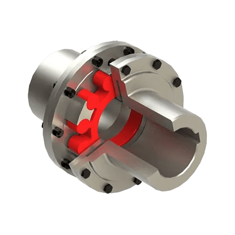 MCS Double-Flange Plum Coupling for Misalignment CompensationFeaturing a double-flange design for direct bolting to equipment flanges, this coupling helps achieve high coaxiality and compensates for radial, angular, and axial misalignments. It offers up to 99% transmission efficiency and electrical insulation.View Product →
- Quick Links
- About
- Products
- Our Service
- News & Events
- Contact
- Products Series
- Flexible Couplings with Non-Elastic Elements
- Flexible Couplings with Metal Elastic Elements
- Flexible Couplings with Non-Metallic Elastic Elements
- Safety Coupling
- Rigid Coupling
- Contact Us
- Tel : +86 511 8572 3800 +86 511 8572 3900
- Mobile : +86 15106109009
- Email : sales@couplingzy.com
- Add:No.1 Zhongye Yingbin Avenue, Gaozi Street, Dantu Economic Development Zone, Zhenjiang City, Jiangsu Province, China.


