:+86 15106109009
:sales@couplingzy.com


 English
  русский
  Español
  عربى
عربى  Português
  Deutsch
  Türk
Türk  Indonesia

Rigid Shaft Coupling Types: Sleeve, Clamp, Flange, and Ring Designs Explained
Content
- 1 What Makes a Coupling Rigid?
- 2 The Main Rigid Shaft Coupling Types
- 3 Rigid Versus Flexible: Knowing Which Family You Need
- 4 How to Choose Among Rigid Coupling Types
- 5 Alignment and Installation Notes
- 6 Where Rigid Couplings Fit Best
- 7 When a Rigid Coupling Is Not the Answer
- 8 Getting the Right Rigid Coupling
Rigid shaft couplings do one job extremely well: they hold two shafts together so the pair turns as a single piece. There is no rubber element to absorb shock, no spring to bend under load and no gap designed in to swallow misalignment. That simplicity is exactly why they appear on line shafts, vertical pump drives, test stands and anywhere alignment can be held tight while torque has to pass through with almost no lost motion.
We build couplings at Zhongye Heavy Industry Technology (Zhenjiang) Co., Ltd., and rigid couplings are one of the smaller groups in our catalogue, next to diaphragm, drum gear, tyre, jaw, chain and safety couplings. Small or not, it is the group customers ask about most once their shafts are already parallel and the only open question is which pattern to bolt on. Here are the rigid shaft coupling types you are likely to meet, what each one asks of your shafts, and how to choose between them.
What Makes a Coupling Rigid?
A coupling counts as rigid when it contains no element intended to compensate for misalignment. Everything in the joint is metal, machined to fit, and the connection is about as stiff in torsion as the shafts themselves. Three things follow from that. Torque capacity per unit of size is high, because there is no elastomer to shear and no cage to distort. Torsional stiffness is high and backlash is close to zero when keys and bolts are done properly, which matters on reversing drives and on machines where lost motion shows up as marks on the product. And alignment tolerance is almost nil. In our experience most rigid patterns are comfortable within roughly 0.05 mm of parallel offset and 0.05 mm per 100 mm of angular error; push far past that and the bearings, not the coupling, pay the bill.
The Main Rigid Shaft Coupling Types
Catalogues divide the rigid family in different ways, but nearly every version comes back to four patterns: sleeve, split-muff or clamp, flange, and ring compression. The real differences are how the coupling grips the shaft and how much room you need to assemble it.
Sleeve (Muff) Coupling
The oldest rigid coupling is a single cylindrical sleeve that slides over both shaft ends. Torque travels through a key in each shaft, while set screws or taper pins hold the sleeve in place axially. It is cheap, compact and easy to machine, which keeps it alive on low-speed line shafts and small gearmotor drives. Its weakness is assembly: the sleeve normally goes on axially, so one shaft has to be free to move, and the same freedom is needed again during maintenance. It suits modest torque at low speed, where the shafts can be aligned once and left alone.
Split-Muff and Clamp Coupling
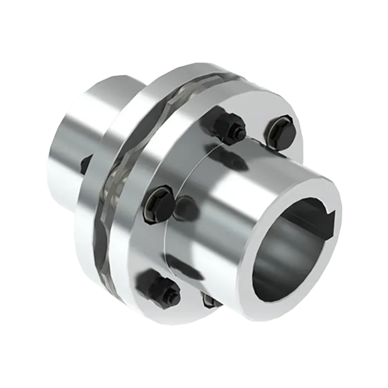
Split the sleeve in two, add bolts across the split, and you have a clamp coupling that goes on without moving either shaft. The halves are machined as a pair, keyed to the shafts and drawn together by bolts that also supply the clamping force. Because it is assembled radially, this pattern is the friendliest rigid option for repairs and for drive trains that cannot be shifted. Our JK and JKW clamp couplings follow exactly this logic, with the JKW version covering a wider clamping range for shafts that are not perfectly to nominal size. Bolt tightening matters more than people expect: uneven torque is a common reason a clamp coupling develops a wobble.
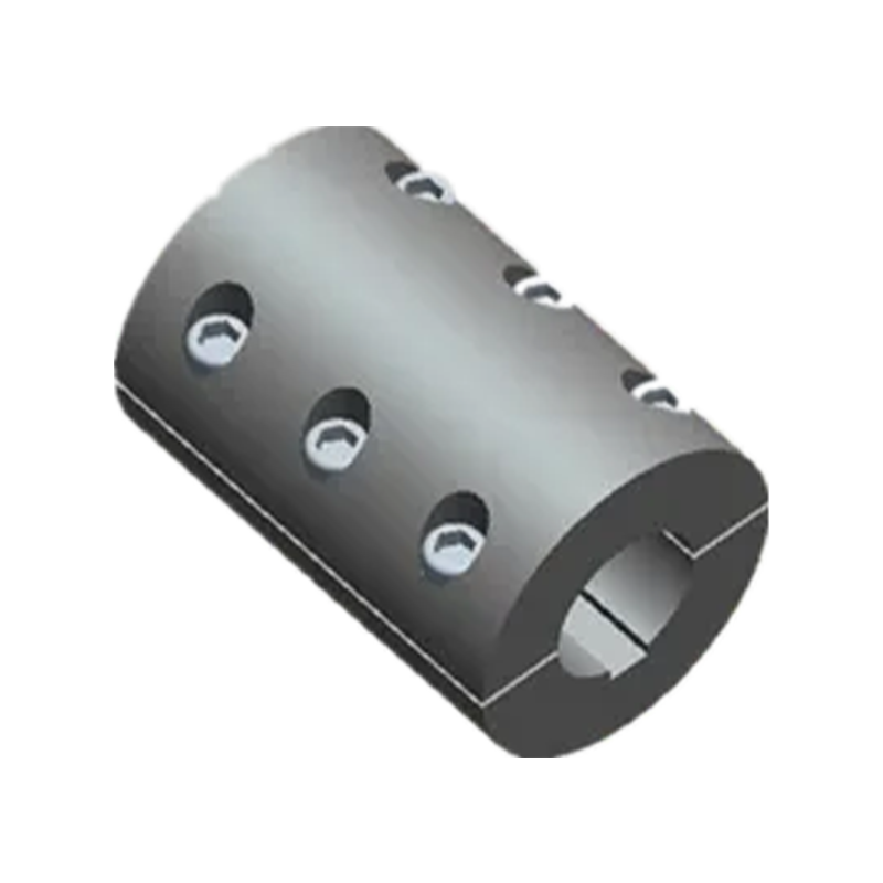 JK and JKW Type Clamp CouplingA rigid clamp coupling assembled radially to avoid moving either shaft, with JK and JKW options covering a wider clamping range.View Product →
Rigid Flange Coupling
Here each shaft carries its own hub with a flange, and the two flanges are bolted face to face. It is the pattern of choice for larger diameters and higher torques, since the bolts can be sized generously and the joint is easy to inspect. Flange couplings are usually described as protected or unprotected, depending on whether the rim covers the bolt heads. The price is machining accuracy: both flanges must be bored and faced so the assembled joint sits square to the shaft centreline, because runout in the flange face becomes a once-per-revolution force on the bearings.
Ring Compression Coupling
A compression, or friction ring, coupling grips by squeezing instead of keying. A split ring or tapered sleeve is compressed around the shaft ends by an outer collar or a ring of bolts, producing a friction joint with no keyway at all. That is a genuine advantage: no keyway means no stress concentration in the shaft, and the grip can be released and reset when parts need repositioning. Keyless designs of this kind are common on reversing drives and on shafts that are already working hard. Torque capacity depends on clamping force and friction, so surface finish and cleanliness of the mating faces are not optional details.
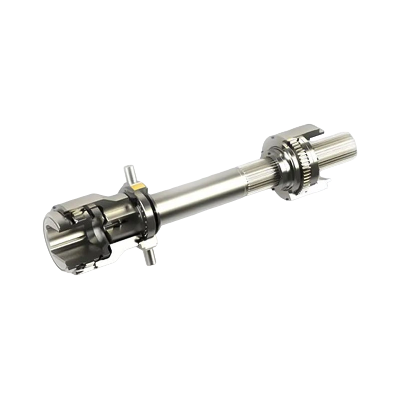
One further point worth knowing: a rigid joint gives nothing under overload, so some designs add a shear pin, a shear ring or a slipping friction disc. If you need rigid stiffness plus protection against jams, a safety coupling is a better answer than a plain sleeve.
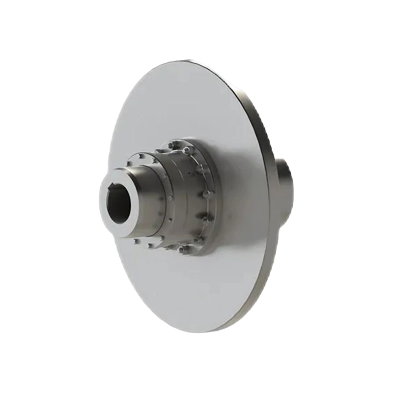
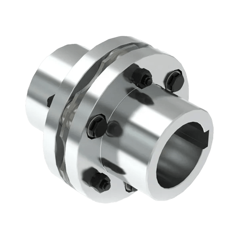 Rigid Coupling Category: Types, Selection and Industrial ApplicationsExplore rigid coupling options such as flange and JK/JKW clamp couplings, with selection guidance for high-torque, precise, backlash-free drives.View Product →
Rigid Versus Flexible: Knowing Which Family You Need
The choice is rarely about torque alone. A rigid coupling transfers torque efficiently, holds timing and usually costs less, but it demands alignment that plenty of real drive trains cannot deliver. The table below sets the rigid patterns side by side, with one flexible option for contrast.
| Coupling type | Torque density | Misalignment tolerance | Assembly | Typical use |
|---|---|---|---|---|
| Sleeve (muff) | Medium | None | Axial slide | Low-speed line shafts |
| Split-muff / clamp | Medium | None | Radial, in place | Repairs and cramped drives |
| Rigid flange | High | None | Bolted flanges | Large shafts, high torque |
| Ring compression | Medium to high | None | Clamped, keyless | Reversing and stressed shafts |
| Drum gear (flexible) | High | Angular and offset | Bolted, lubricated | Mill, crane and mine drives |
If your shafts cannot be brought within a few hundredths of a millimetre, a rigid coupling is not a challenge to overcome but the wrong family. Drum gear, diaphragm, tyre, chain and jaw couplings exist to absorb that error, so it is worth settling the flexibility question before you settle the pattern.
How to Choose Among Rigid Coupling Types
Once the drive can be aligned, selection becomes a short list of checks. These are the ones we run through with customers before quoting:
- Torque and service factor. Start from the driver rating, then apply the service factor for shock, starts and duty cycle.
- Bore, keyway and shaft material. Confirm the bores before you compare patterns; a keyless grip may be the only option on a slim shaft.
- Speed. Rigid couplings balance well, but fast machines are far less forgiving of runout at the joint.
- Alignment you can actually achieve. Measure the drive as built, not as drawn.
- Assembly and service access. Sleeve needs axial room, clamp and flange need radial room for tools.
- Environment. Dust, water, washdown and temperature decide materials and surface treatment.
- Stiffness and backlash. Timing-critical or reversing duties usually rule out anything with play.
If you would like a longer version of this reasoning, our note on how to select the appropriate coupling walks through the same sequence with more examples.
Alignment and Installation Notes
Rigid couplings reward a careful installation more than any other family, and the good news is that the work is straightforward:
- Measure with a dial indicator or laser tool; do not judge alignment by eye or by feel.
- Correct angular error first, then parallel offset, then repeat until both are inside tolerance.
- Allow for thermal growth if one machine runs noticeably hotter than the other.
- Re-check alignment after the first few hours of running and again after the first week.
- Keep keys, bolt faces and clamp surfaces clean and dry, and tighten in a cross pattern.
Where Rigid Couplings Fit Best
- Vertical pump drives where the motor sits directly above the pump.
- Line shafting in paper, textile and conveying equipment.
- Machine tool and test stand drives that need precise timing.
- Torque calibration rigs and dynamometer installations.
- Small gearmotor drives on low-speed, lightly loaded equipment.
- Any shaft connection where a keyless friction grip protects a highly stressed shaft.
These are the duties where their stiffness is an asset rather than a liability. Take the alignment away, and the same coupling that ran quietly for years can start eating bearings within weeks.
When a Rigid Coupling Is Not the Answer
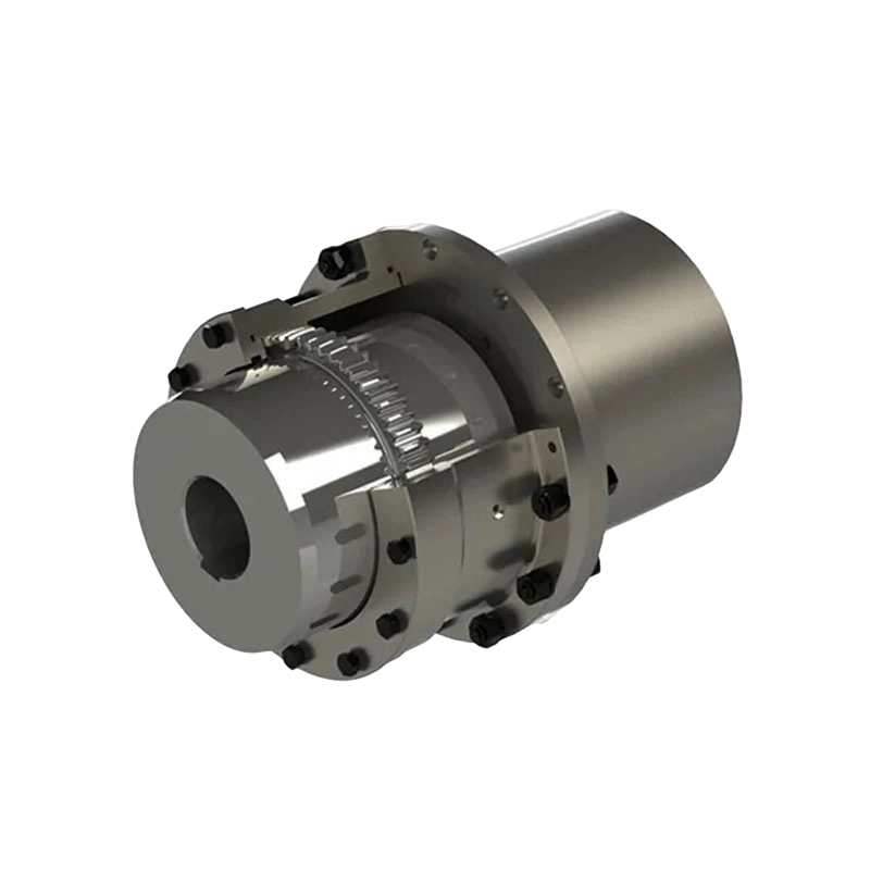
Metallurgical, mining, crane and port drives rarely hold alignment tightly enough for a rigid joint. Thermal movement, foundation settlement and heavy radial loads all push the shafts out of line, and that is precisely the territory of drum gear and other flexible designs, which tolerate angular and offset error while still carrying high torque.
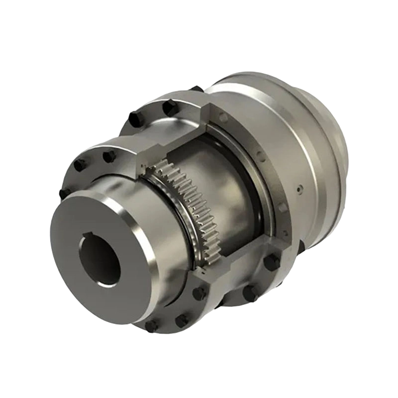 GA Drum Gear Coupling for Heavy-Duty Flexible Drive SystemsHeavy-duty flexible gear coupling with a drum-shaped sleeve for angular, radial and axial misalignment, available in GA1 through GA30 models.View Product →
Getting the Right Rigid Coupling
We have been making couplings in Zhenjiang since 2014, with a heavy workshop and a precision workshop under the same roof, so standard patterns and non-standard shaft connections are both everyday work for us. If you can share the shaft diameters, the torque, the speed and the space you have around the joint, we can usually tell you within a day whether a sleeve, clamp, flange or ring compression design is the sensible choice, or whether you should be looking at a flexible coupling instead. If you would like to talk it through, contact our team and send the drawing or the duty details.
- Quick Links
- About
- Products
- Our Service
- News & Events
- Contact
- Products Series
- Flexible Couplings with Non-Elastic Elements
- Flexible Couplings with Metal Elastic Elements
- Flexible Couplings with Non-Metallic Elastic Elements
- Safety Coupling
- Rigid Coupling
- Contact Us
- Tel : +86 511 8572 3800 +86 511 8572 3900
- Mobile : +86 15106109009
- Email : sales@couplingzy.com
- Add:No.1 Zhongye Yingbin Avenue, Gaozi Street, Dantu Economic Development Zone, Zhenjiang City, Jiangsu Province, China.


