:+86 15106109009
:sales@couplingzy.com


 English
  русский
  Español
  عربى
عربى  Português
  Deutsch
  Türk
Türk  Indonesia

What Is a Rigid Coupling? Definition, Function, and Design
Content
- 1 What Is a Rigid Coupling?
- 2 No Compensation Capability Is Built Into the Design, Not Worked Around
- 3 High Stiffness Enables Torque Transmission Without Lag
- 4 The Absence of Buffering Makes Shock Sensitivity a Design Concern
- 5 Flange and Clamp Designs Cover the Two Common Rigid Coupling Types
- 6 When a Rigid Coupling Fits Better Than a Flexible One
What Is a Rigid Coupling?
A rigid coupling is a mechanical connector that joins two shafts into what behaves as a single continuous shaft, transmitting torque directly with no built-in flex to absorb misalignment, axial movement, or shock. Flexible couplings rely on elastomeric elements or thin metal discs to accommodate small positioning errors between shafts; a rigid coupling instead depends on the two connected shafts already being aligned to a tight tolerance before installation ever begins.
No Compensation Capability Is Built Into the Design, Not Worked Around
Every coupling in rotating machinery solves one problem: connecting a driver shaft — a motor or engine output — to a driven shaft on a pump, gearbox, or similar machine. A rigid coupling solves this through a solid connection that transfers torque with no internal give, so it cannot compensate for radial offset, angular misalignment, or axial float between shaft centerlines. That limitation traces back to the coupling body itself, machined as a solid or near-solid section with no path for the kind of flex a diaphragm or elastomeric element provides in a flexible design — it isn't a shortcoming engineers accommodate after installation, it's a direct structural consequence of how the part is built.
Installation Tolerance Becomes the Deciding Factor
Since the coupling itself absorbs none of the misalignment, shaft centering during installation needs to land within a tight tolerance band — often specified in thousandths of an inch or fractions of a millimeter, depending on shaft diameter and rotational speed, per API 610 alignment guidance commonly referenced for pump drivetrains. Dial indicator alignment or laser shaft alignment equipment typically verifies this centering before a rigid coupling gets torqued into place, since even a small angular offset left uncorrected transfers straight into bearing loads and vibration once the shaft starts turning under load.
High Stiffness Enables Torque Transmission Without Lag
The same solid construction that removes flexibility also delivers a rigid coupling's main working advantage: torsional stiffness. Torque applied at the driver shaft reaches the driven shaft with essentially no elastic windup or backlash in between, a property that matters where precise timing between shafts is required — synchronized multi-shaft drives or positioning equipment where rotational lag between input and output throws off calibration. Flexible couplings built around rubber elements, by comparison, show a measurable degree of torsional windup under load as the elastomer compresses before fully transmitting torque, an effect negligible in general power transmission but relevant enough in precision motion control that engineers specify against it directly.
| Characteristic | Rigid Coupling | Flexible Coupling |
|---|---|---|
| Misalignment Tolerance | None — requires precise alignment | Accommodates minor offset |
| Torsional Stiffness | High, no windup or backlash | Some windup under load |
| Shock Absorption | None | Dampens vibration and shock loads |
The Absence of Buffering Makes Shock Sensitivity a Design Concern
Without an elastomeric or flexible element to absorb sudden torque spikes, a rigid coupling passes shock loads straight through to connected components — gears, bearings, and shaft seats each take the full force of a sudden load change rather than having part of that energy dissipated inside the coupling itself. That characteristic makes rigid couplings a poor match for equipment with frequent starts, stops, or reversing loads, such as certain conveyor or crusher drives where impact loading is routine rather than occasional. Steady, continuous-load applications with minimal starting torque variation — long-shaft pump drives or precisely aligned machine tool spindles, for example — are where this lack of buffering matters least, since operating conditions there rarely introduce the kind of shock a flexible coupling would otherwise need to absorb.
Flange and Clamp Designs Cover the Two Common Rigid Coupling Types
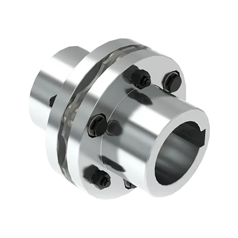
A flange coupling uses two separate hub pieces, each keyed or press-fit onto one of the two shaft ends, bolted together face-to-face through a matching flange pattern. This construction allows straightforward disassembly during maintenance, since removing the connecting bolts separates the two shaft sections cleanly without needing to slide the coupling axially off either shaft — a practical benefit on equipment where axial shaft movement during teardown isn't an option.
A clamp coupling, sometimes called a split coupling, uses a single cylindrical sleeve split along its length, clamping around both shaft ends where they meet inside the sleeve. Tightening the clamp bolts compresses the sleeve onto both shafts at once, forming a rigid connection that in some designs doesn't even require keyways, depending on torque requirements and shaft diameter specified by the manufacturer. Flange couplings tend to suit situations calling for disassembly without shifting either shaft axially, while clamp couplings fit better where the shaft simply can't move axially during installation or removal — though both designs share the same underlying requirement regardless of which is chosen, since neither compensates for misalignment once installed, and pre-installation alignment work carries the same weight either way.
When a Rigid Coupling Fits Better Than a Flexible One
Choosing between a rigid and a flexible coupling generally comes down to whether shaft alignment can realistically hold to a tight tolerance across the equipment's operating life, and whether the application generates vibration or shock loads that need dampening rather than direct transmission. Rigid couplings tend to fit long, continuously supported shafts — vertical pump shafts running through multiple bearing supports, for instance — where the shaft itself is engineered to stay aligned along its length rather than relying on the coupling to correct for drift after the fact. Shorter shaft spans between machines, more frequent maintenance disassembly, or foundation work with looser tolerances generally push the decision toward flexible coupling designs instead, since the ongoing cost of holding rigid-coupling-level alignment can outweigh the stiffness advantage a rigid design offers in that particular setup.
In practice, the decision tends to settle around a handful of project-specific questions rather than a fixed rule: whether shaft alignment can be verified and held within the coupling manufacturer's tolerance over the equipment's service life, whether the drivetrain experiences frequent starts, stops, or reversing loads that would introduce shock the coupling can't absorb, whether precise torsional timing between shafts matters for how the machine operates, and whether flange or clamp geometry better suits how the coupling will need to come apart during future maintenance. Weighing these together against the specific drivetrain, rather than defaulting to one coupling type across every application, is what determines whether a rigid design actually holds up over the equipment's working life.
- Quick Links
- About
- Products
- Our Service
- News & Events
- Contact
- Products Series
- Flexible Couplings with Non-Elastic Elements
- Flexible Couplings with Metal Elastic Elements
- Flexible Couplings with Non-Metallic Elastic Elements
- Safety Coupling
- Rigid Coupling
- Contact Us
- Tel : +86 511 8572 3800 +86 511 8572 3900
- Mobile : +86 15106109009
- Email : sales@couplingzy.com
- Add:No.1 Zhongye Yingbin Avenue, Gaozi Street, Dantu Economic Development Zone, Zhenjiang City, Jiangsu Province, China.


