:+86 15106109009
:sales@couplingzy.com


 English
  русский
  Español
  عربى
عربى  Português
  Deutsch
  Türk
Türk  Indonesia

How Does A Rigid Coupling Work And Where Is It Used?
Content
- 1 What A Rigid Coupling Is And How It Transmits Torque
- 2 No Compensation Capability And Alignment Requirements
- 3 Structural Rigidity And Torque Capacity
- 4 Absence Of Buffering And Sensitivity To Impact
- 5 Flange Couplings And Clamp Couplings As Representative Types
- 6 Related Overload Protection In Friction-Type Safety Couplings
- 7 Applications Across Industrial Equipment
- 8 Factors To Consider When Selecting A Rigid Coupling
What A Rigid Coupling Is And How It Transmits Torque
A rigid coupling joins two shafts into what functions as a single continuous shaft, transmitting torque directly through a solid connection without any built-in mechanism for absorbing shaft misalignment. This differs fundamentally from flexible or safety-type couplings, which include some form of compensation or slip capability. Because a rigid coupling transfers motion and load in a fixed, unyielding manner, the design depends entirely on precise alignment between the connected shafts to function correctly over time.
No Compensation Capability And Alignment Requirements
A defining characteristic of a rigid coupling is that it cannot compensate for radial, axial, or angular displacement between the two connected shafts, which means installation must be precisely centered before the coupling is put into service. Any deviation from true alignment during installation does not get absorbed by the coupling itself, unlike a flexible coupling designed to accommodate a certain range of misalignment. Instead, misalignment in a rigid-coupled system transfers directly into the bearings and shaft, which can accelerate wear if the initial setup is not carried out with careful measurement and adjustment.
Structural Rigidity And Torque Capacity
Strong rigidity is a core feature of this coupling type, supported by a simple structure and high stiffness that allows it to transmit large torques without lag or backlash between the driving and driven shafts. Because there is no flexible element absorbing motion, torque transfer through a rigid coupling happens with minimal rotational delay, which matters for applications where precise timing between connected shafts is part of the overall system design. This stiffness also means that torsional load is carried through the coupling body itself rather than distributed across a cushioning material, placing greater importance on selecting a coupling sized appropriately for the torque involved.
Absence Of Buffering And Sensitivity To Impact
Rigid couplings provide no buffering or vibration reduction function, which leaves the connected system sensitive to sudden impact loads that a flexible or damped coupling design would otherwise help absorb. This characteristic shapes where rigid couplings are typically applied, since equipment exposed to frequent shock loading or fluctuating torque generally benefits more from a coupling type with some cushioning capacity. In steady, low-vibration operating conditions, however, this lack of buffering is less of a concern, and the direct torque transfer becomes an advantage rather than a limitation.
Core Rigid Coupling Characteristics
- No radial, axial, or angular displacement compensation
- Simple, high-stiffness structure for large torque transmission
- Minimal rotational lag or backlash during operation
- No buffering, making the system sensitive to impact loads
- Precise shaft centering required during installation
Flange Couplings And Clamp Couplings As Representative Types
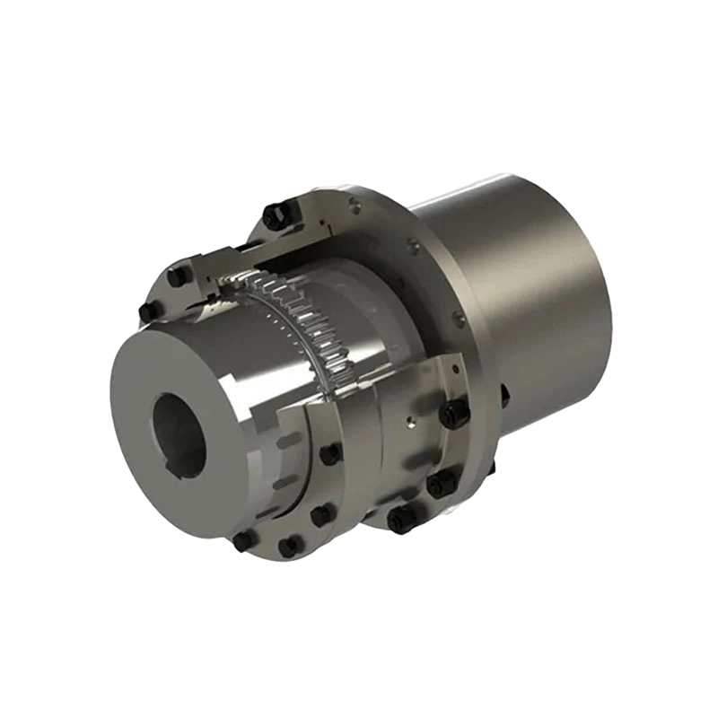
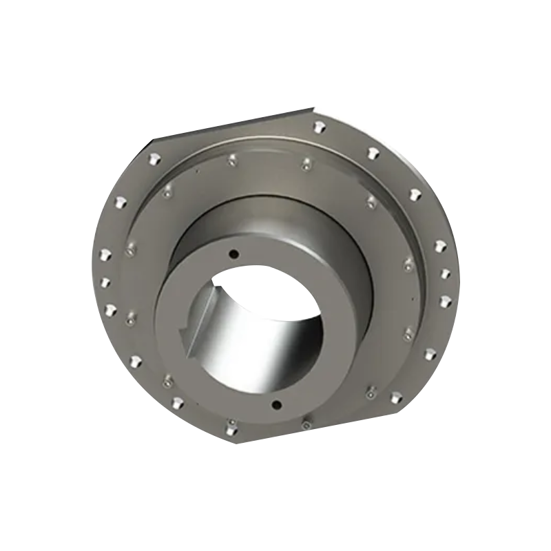
Flange couplings and clamp couplings represent the two common forms of rigid coupling used across industrial equipment. A flange coupling connects two shaft-mounted flange halves through a ring of bolts, distributing torque evenly across the bolt pattern while forming a joint stiff enough to behave as part of a continuous shaft line. A clamp coupling, sometimes referred to as a split or sleeve coupling, encloses the shaft ends within a split housing that is tightened with bolts, gripping the shaft surface through clamping force rather than a keyed or flanged connection.
Clamp-style rigid couplings, such as JK or JKW type designs, are generally favored where installation and removal need to happen without sliding the coupling along the shaft length, since the split housing can be opened and closed around the shaft in place. Flange couplings, by comparison, tend to suit applications where a bolted joint offers easier disassembly for maintenance on longer shaft runs.
Related Overload Protection In Friction-Type Safety Couplings
While a standard rigid coupling has no built-in overload protection, a related category of friction-type safety coupling addresses this gap by allowing controlled slip once torque exceeds a preset threshold, generally covering a nominal torque range from about 6.3 N·m to 9,500 N·m depending on the model. When system load surpasses this preset value, the friction pair slips rather than transmitting the full overload force downstream, which helps isolate motors and connected equipment from sudden torque spikes. Spring nut adjustment on these designs allows the torque threshold to be set to match the specific requirements of a given drive system.
Friction materials used in this type of coupling are generally selected for wear resistance and heat tolerance, since the friction pair experiences repeated contact and slip cycles over the service life of the equipment. Transmission efficiency in these designs is commonly maintained above 95 percent even after repeated protection events, reflecting the durability built into the friction material and spring assembly. This combination of compact structure, displacement tolerance during slip events, and reduced shock transfer makes friction-type safety couplings a common companion technology in drive systems where rigid couplings are also present.
Applications Across Industrial Equipment
| Coupling Type | Connection Method | Typical Setting |
|---|---|---|
| Flange Coupling | Bolted flange halves | Long shaft runs, pumps, compressors |
| Clamp Coupling | Split housing clamping force | Machine tools, conveyor drives |
Rigid couplings are generally applied in machine tools, pumps, compressors, and conveyor drive systems where shaft alignment can be controlled precisely during installation and where operating conditions remain relatively steady without frequent shock loading. Precision equipment, including certain servo-driven systems, also relies on rigid couplings where the absence of backlash supports accurate motion transfer between connected components.
Factors To Consider When Selecting A Rigid Coupling
Confirming that shaft alignment can be achieved and maintained within a tight tolerance is a starting point before committing to a rigid coupling, since any ongoing misalignment translates directly into bearing and shaft wear rather than being absorbed by the coupling. Torque requirements also need to be matched carefully to the coupling's rated capacity, given that a rigid design carries load through a stiff structure without a flexible element to distribute unexpected spikes.
For systems where impact loading or occasional overload risk is a concern, pairing a rigid coupling with a separate protective device, such as a friction-type safety coupling, is a common approach to combining stiff torque transmission with a layer of overload protection. Reviewing whether a flange or clamp design better suits the maintenance access and installation process at a given site also helps narrow the selection between the two representative rigid coupling types.
- Quick Links
- About
- Products
- Our Service
- News & Events
- Contact
- Products Series
- Flexible Couplings with Non-Elastic Elements
- Flexible Couplings with Metal Elastic Elements
- Flexible Couplings with Non-Metallic Elastic Elements
- Safety Coupling
- Rigid Coupling
- Contact Us
- Tel : +86 511 8572 3800 +86 511 8572 3900
- Mobile : +86 15106109009
- Email : sales@couplingzy.com
- Add:No.1 Zhongye Yingbin Avenue, Gaozi Street, Dantu Economic Development Zone, Zhenjiang City, Jiangsu Province, China.


