:+86 15106109009
:sales@couplingzy.com


 English
 русский
 Español
 عربى
 Português
 Deutsch
 Türk
 Indonesia


Coupling Gears Explained: Gear Coupling Types, Selection and Maintenance
Content
- 1 What "Coupling Gears" Really Refers To
- 2 How the Mesh Transmits Torque and Absorbs Misalignment
- 3 The Variants You Will Actually See
- 4 Selection: The Numbers That Decide the Outcome
- 5 Special Duties: Brakes, Long Spans and Vertical Shafts
- 6 Installation and Maintenance Habits That Pay Off
- 7 Where These Couplings Earn Their Place
Stand beside the main drive of a rolling mill, a stacker-reclaimer or a ladle crane and the odds are good that the shaft connection in front of you is a gear coupling. Many people search for that part simply as "coupling gears", which describes it well enough: two sets of crowned teeth meshing inside a sleeve, quietly carrying the load.
This article covers the toothed side of shaft connections — how the mesh carries torque, which variants exist, how engineers choose between them, and the habits that keep one running for years instead of months.
What "Coupling Gears" Really Refers To
The phrase gets used in two overlapping ways. Sometimes it means the gear teeth themselves: the external, slightly barrel-shaped teeth on each hub and the matching internal teeth cut into the sleeve. Sometimes it means the whole family of gear-type couplings, as distinct from jaw, tyre, diaphragm or chain types.
One clarification is worth making early. Coupling gears are not gearbox gears. They do not change speed or multiply torque, and there is no continuous rolling contact the way a reduction stage has. Their job is compensation — passing torque from one shaft to another while absorbing angular, radial and axial offset, plus the small movements that thermal growth and load deflection introduce.
In our catalogue these products sit under flexible couplings with non-elastic elements. "Non-elastic" is not a comment on performance; it simply means the flexibility comes from the geometry of the tooth mesh rather than from a rubber element that deforms or a thin metal disc that flexes.
How the Mesh Transmits Torque and Absorbs Misalignment
A gear coupling is a short assembly: two hubs keyed or shrink-fitted onto the shaft ends, each carrying external teeth; one or two sleeves with internal teeth bridging the gap; seals at each end; and a charge of grease or oil that those seals exist to protect.
The teeth are crowned, meaning slightly barrel-shaped across the face width, and that single detail is what makes the design work. Because the flanks are curved, contact stays reasonably even when the two shafts are not perfectly collinear, and the sleeve can rock without digging a line load into one edge of a tooth. In practice a single mesh absorbs roughly one to one and a half degrees of angular misalignment and a few millimetres of axial float, depending on size and series.
Under misalignment the teeth slide rather than roll, so the mesh is a sliding contact and lubrication is part of the load path, not an accessory. A dry or contaminated coupling rarely fails suddenly; it wears, backlash opens up, the tooth profile changes, and eventually the drive sounds and behaves differently. Double-engagement versions, with a floating sleeve spanning two meshes, double the misalignment capacity and suit applications where alignment is hard to hold.
The Variants You Will Actually See
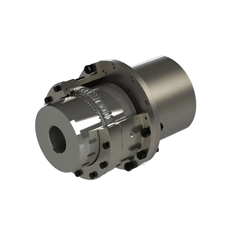
The core design has been extended in a handful of directions, and those extensions usually decide which drawing the workshop pulls. The basic GA, GB and GC series cover straightforward motor-to-machine connections.
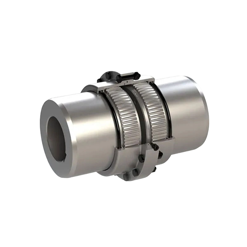 GA Series Drum Gear CouplingA baseline flexible gear coupling for direct motor-to-machine connections, using meshing toothed hubs and a drum sleeve to accommodate misalignment.View Product →
| Variant | What it adds | Typical duty |
|---|---|---|
| GA / GB / GC | Standard double-engagement drum gear coupling | General motor-to-machine drives |
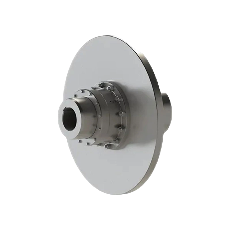
| GBL, GBLZ, GCL | Brake wheel on the sleeve | Hoisting and travel drives with shoe brakes |
| GAP, GCP | Brake disc interface | Disc-braked cranes and winches |
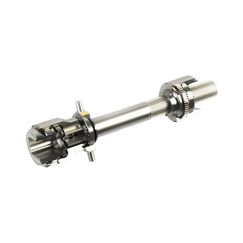
| GAZ, GBZ, GCJ | Intermediate shaft between two meshes | Wide shaft gaps, easier alignment in service |
| GCT | Intermediate sleeve | Long spans where weight matters |
| GCC | Vertical installation arrangement | Vertical pumps, mixers, roll adjustment drives |
| GBD | Motor shaft extension fit | Direct motor connection without a separate half |
| NC | Nylon inner gear ring | Lighter duties where grease-free running suits |
It helps to read these as one design with different mounting provisions. The teeth, the seals and the lubrication requirement stay the same; what changes is how the coupling meets the brake, the shaft span or the machine frame.
Selection: The Numbers That Decide the Outcome
Selection is rarely about finding the biggest coupling that fits. It is about matching a handful of parameters, and this is the order we usually work through.
- Torque and service factor. Start from the driven machine's rated torque, then apply a factor for shock, starts per hour and reversing duty. Mills, crushers and hoists punish a coupling far more than a fan does.
- Bore, keyway and fit. Available hub bores cap the selection quickly. Confirm whether the shaft needs a key, a shrink fit or a spline, and check the maximum bore for the size chosen.
- Misalignment budget. Add installation tolerance, thermal growth and expected foundation movement. If the total sits close to the coupling's limit, change the arrangement rather than the coupling.
- Speed and axial float. Higher speeds need balanced assemblies and, above a certain point, oil feed rather than grease packing. Drives that must move axially need the float designed in so thrust never reaches a bearing.
- Environment. Dust, water, high ambient temperature and washdown all change the seal and lubricant choice.
- Interfaces. If a brake acts through the coupling, wheel or disc diameter and mounting pattern belong in the specification from the start.
Oversizing carries a cost that rarely shows on the quotation: a bigger coupling is heavier, adds inertia, holds more lubricant and takes longer to inspect.
Special Duties: Brakes, Long Spans and Vertical Shafts
Brake integration is the most common special requirement we see. A brake wheel on the coupling sleeve saves a separate brake drum and shortens the drive train, which matters on crane hoisting and on travel drives where space between gearbox and motor is tight.
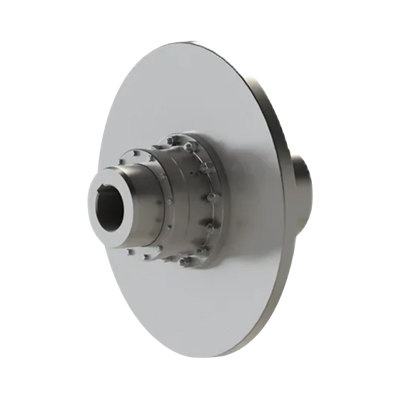 GBL Drum Gear Coupling with Integrated Brake WheelIntegrates a brake wheel into the coupling sleeve for crane hoisting and tight travel drives, saving a separate brake drum.View Product →
Long spans are the second. When motor and machine sit further apart than one sleeve can bridge, an intermediate shaft or intermediate sleeve keeps both meshes working as intended instead of forcing a single oversized coupling across the gap.
 GCT Drum Gear Coupling for Intermediate Sleeve ConnectionsBridges longer motor-to-machine spans with an intermediate sleeve, keeping both gear meshes aligned while compensating axial, radial and angular misalignment.View Product →
Vertical machines are the third. Gravity acts along the shaft axis there, so the coupling and its lubrication path are configured differently from a horizontal drive.
Installation and Maintenance Habits That Pay Off
Most gear coupling problems we are asked to look at trace back to installation or lubrication rather than to the teeth themselves. A few habits do most of the work:
- Align the shafts properly before bolting anything up, and record the readings. The coupling can absorb misalignment, but using that capacity instead of aligning shortens life.
- Use the specified lubricant in the specified quantity. Too little starves the mesh; too much can push past the seals.
- Inspect the seals at every lubrication interval. A failed seal lets grit in and grease out, and the mesh wears quickly afterwards.
- Read the wear pattern, not just the backlash. A pattern concentrated at one end of the tooth points to alignment; an even polish says the mesh is behaving.
- Keep simple records of vibration, temperature and noise after each service. Trends catch problems earlier than inspections do.
Where These Couplings Earn Their Place
The industries that lean on gear couplings combine high torque with imperfect alignment: metallurgical plant, mining and crushing circuits, water conservancy equipment, cranes, paper machines and port handling machinery. The common thread is not speed or precision but load — drives where torsional shock is normal and downtime is expensive.
We build them in Zhenjiang, where our workshops have been turning out couplings since 2014, split between a heavy shop for large bodies and a precision shop for the smaller fits and tooth work. Alongside the standard drum gear coupling range we take on non-standard designs, which in practice means a good many brake wheels, intermediate shafts and bore arrangements that appear in no catalogue.
If you are working through a selection and the numbers do not line up neatly, send us the duty details — torque, speeds, shaft sizes and the space available. Comparing options against a real drive is usually faster than reading a catalogue page.
Gear couplings are easy to overlook because they work quietly. Understanding what the coupling gears inside them actually do — how crowned teeth carry load, why lubrication belongs to the design, and which variant suits a given span or brake arrangement — makes selection and maintenance far less mysterious, and keeps the drive train running the way it was intended.
- Quick Links
- About
- Products
- Our Service
- News & Events
- Contact
- Products Series
- Flexible Couplings with Non-Elastic Elements
- Flexible Couplings with Metal Elastic Elements
- Flexible Couplings with Non-Metallic Elastic Elements
- Safety Coupling
- Rigid Coupling
- Contact Us
- Tel : +86 511 8572 3800 +86 511 8572 3900
- Mobile : +86 15106109009
- Email : sales@couplingzy.com
- Add:No.1 Zhongye Yingbin Avenue, Gaozi Street, Dantu Economic Development Zone, Zhenjiang City, Jiangsu Province, China.


