:+86 15106109009
:sales@couplingzy.com


 English
  русский
  Español
  عربى
عربى  Português
  Deutsch
  Türk
Türk  Indonesia

Why Is High-Performance Brake Drum Gear Coupling the Ultimate Solution for Maximizing Heavy-Duty Industrial Reliability and Safety?
Content
- 1 Understanding Brake Drum Gear Couplings
- 2 Core Components and Design Architecture
- 3 Operating Principles and Torque Transmission Mechanics
- 4 Material Engineering and Construction Standards
- 5 Comparison with Alternative Coupling and Braking Configurations
- 6 Common Application Scenarios
- 7 Installation and Alignment Best Practices
- 8 Maintenance and Inspection Practices
- 9 Selection Criteria for Engineers and Buyers
- 10 Emerging Trends in Coupling and Braking Technology
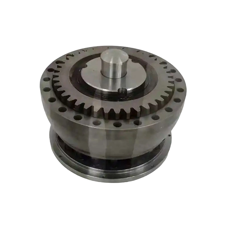
Industrial power transmission systems frequently require components that serve more than a single mechanical function, particularly in applications involving high torque loads, variable operating conditions, and the need for reliable braking integration. The Heavy-Duty Brake Drum Gear Coupling represents a specialized engineering solution that combines the torque transmission capability of a gear coupling with the braking functionality of an integrated brake drum surface, allowing a single component to serve dual mechanical purposes within rotating equipment assemblies. This article provides a detailed technical examination of this coupling category, covering its design principles, operating mechanisms, material engineering, application scenarios, and the practical considerations relevant to engineers and maintenance professionals responsible for specifying and maintaining this equipment.
Understanding Brake Drum Gear Couplings
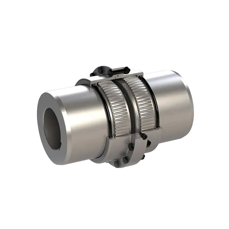
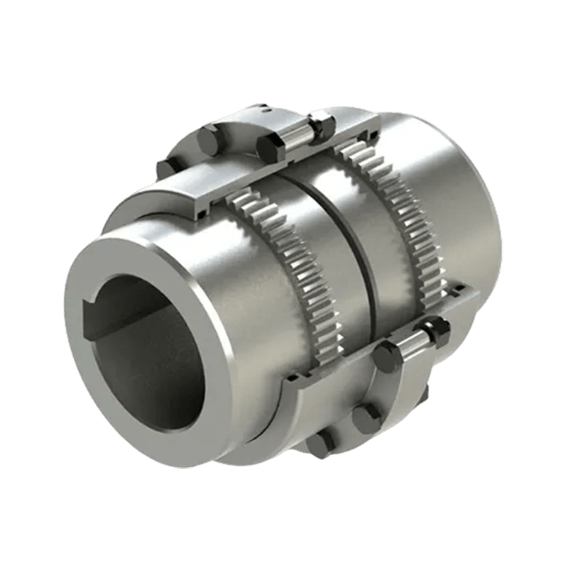
A gear coupling is a mechanical device used to connect two rotating shafts, typically between a driving component such as an electric motor and a driven component such as a gearbox, pump, or conveyor system, while accommodating a degree of angular, parallel, or axial misalignment between the connected shafts. Gear couplings achieve this flexibility through internal gear teeth that mesh with corresponding external teeth on a mating hub or sleeve, allowing limited relative movement between the coupling halves while still transmitting substantial torque loads.
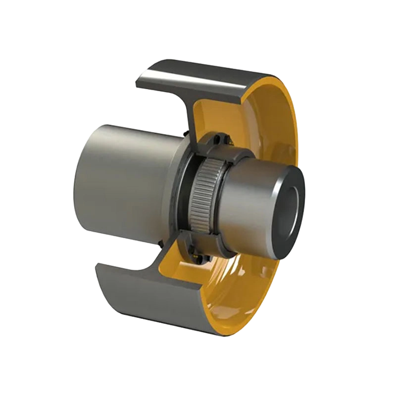
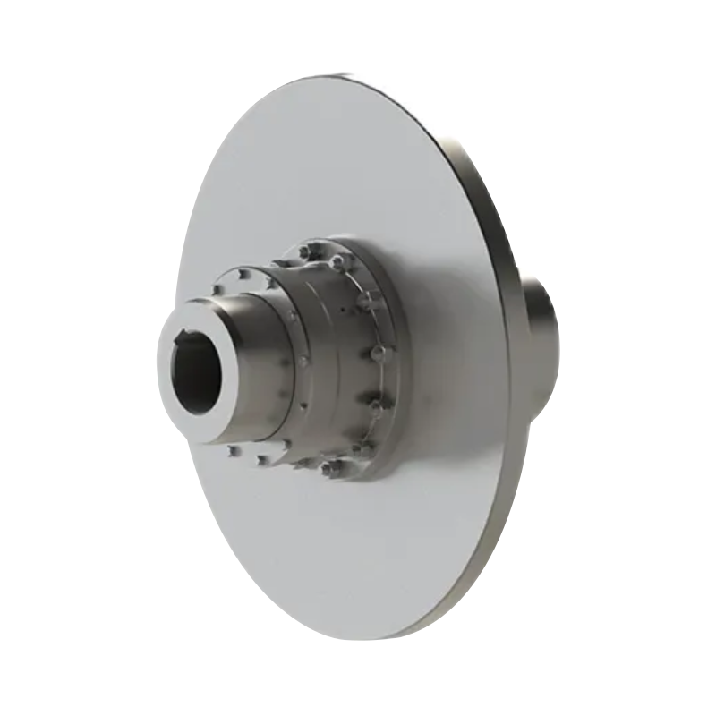
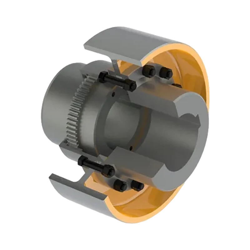
A brake drum gear coupling extends this basic functionality by incorporating a machined brake drum surface directly onto one half of the coupling assembly, typically positioned on the outer diameter of one coupling hub. This integrated drum surface allows a brake shoe assembly to engage the coupling directly, providing braking or holding torque at the coupling location rather than requiring a separate brake drum mounted elsewhere on the shaft. This dual-function design reduces the overall number of components required within the drivetrain, simplifies shaft layout, and can reduce the axial length required for the complete power transmission assembly.
The heavy-duty designation applied to this coupling category reflects construction specifications intended for demanding industrial applications involving high torque transmission, frequent braking cycles, elevated operating temperatures, or exposure to harsh environmental conditions. These couplings are typically constructed from forged or high-grade cast steel components, engineered to withstand substantial mechanical stress over extended service periods within continuous duty industrial operations.
Core Components and Design Architecture
Understanding the functional integration achieved by a brake drum gear coupling requires examining its individual components and how they work together within the overall assembly.
Gear Hub and Sleeve Assembly
The fundamental torque transmission mechanism relies on two primary components, a gear hub keyed or otherwise secured to each connected shaft, and a sleeve featuring internal gear teeth that mesh with external teeth machined onto the hub. The crowned tooth profile commonly used in gear coupling design allows for a degree of angular misalignment between the connected shafts while maintaining continuous gear tooth engagement, distributing torque loads evenly across the meshing surface even when perfect shaft alignment cannot be achieved or maintained over time.
Integrated Brake Drum Surface
The defining feature of this coupling category is the precision-machined cylindrical surface incorporated into one coupling half, engineered to specific dimensional tolerances to ensure consistent, predictable contact with the mating brake shoe assembly. This surface typically undergoes hardening treatment to resist wear from repeated brake shoe contact, since the drum surface must maintain dimensional accuracy and surface finish quality throughout thousands of braking cycles over the equipment's operational lifespan.
Brake Shoe and Actuation Mechanism
The brake shoe assembly, positioned externally around the integrated drum surface, typically incorporates friction lining material bonded or riveted to a shoe backing structure, actuated through hydraulic, pneumatic, electromagnetic, or mechanical spring-applied mechanisms depending on the specific application requirements. When actuated, the brake shoes press against the rotating drum surface, generating friction force that either slows rotational movement or holds the shaft stationary against applied load.
Lubrication System
Because the internal gear teeth experience continuous relative sliding motion during operation, particularly under misaligned conditions, proper lubrication is essential to prevent premature wear. Gear couplings typically incorporate either continuous grease lubrication, sealed within the coupling housing using appropriate seal designs, or in some heavy-duty applications, continuous oil lubrication systems that provide ongoing cooling and lubrication to the meshing gear teeth during extended operating periods.
Seals and Retention Components
Seal assemblies positioned at the coupling housing prevent lubricant loss while also excluding environmental contaminants such as dust, moisture, or debris from entering the gear mesh area. Retaining rings, bolts, or other mechanical fasteners secure the coupling sleeve components together, and these fasteners must be engineered to withstand the combined torque transmission and braking loads experienced during operation without loosening over time.
Operating Principles and Torque Transmission Mechanics
The functional performance of a heavy-duty brake drum gear coupling depends on the interaction between its torque transmission and braking subsystems, each governed by distinct mechanical principles that must be carefully balanced during design and specification.
Torque Transmission Through Gear Mesh
As the driving shaft rotates, torque transfers through the keyed connection into the gear hub, then through the meshing gear teeth into the coupling sleeve, and finally through the corresponding connection into the driven shaft. The crowned tooth geometry allows this torque transmission to continue reliably even as shaft alignment shifts slightly during operation due to thermal expansion, foundation settling, or normal mechanical tolerances within the broader drivetrain assembly.
Misalignment Accommodation
Gear couplings are typically rated for specific angular and parallel misalignment tolerances, expressed in terms of allowable degrees of angular deviation or millimeters of parallel offset between connected shafts. Operating within these specified tolerances helps ensure even load distribution across the gear teeth and prevents the accelerated wear that can result from excessive misalignment conditions exceeding the coupling's design parameters.
Braking Torque Generation
When the integrated brake system is actuated, friction generated between the brake shoe lining and the drum surface converts rotational kinetic energy into heat, gradually reducing shaft rotational speed or, in holding applications, resisting rotational movement entirely to maintain the shaft in a stationary position against applied load, such as preventing unintended movement of a suspended load on a crane or hoist system.
Thermal Management Considerations
Repeated or extended braking cycles generate substantial heat at the drum and shoe interface, and this thermal energy must be adequately dissipated to prevent excessive temperature buildup that could degrade friction lining performance, cause thermal distortion of the drum surface, or affect the properties of lubricant within the adjacent gear coupling components. Heavy-duty designs often incorporate additional surface area, cooling fins, or ventilation features to support effective heat dissipation during demanding braking duty cycles.
Material Engineering and Construction Standards
The demanding service conditions associated with heavy-duty industrial applications require careful material selection throughout the coupling assembly, balancing strength, wear resistance, and manufacturing practicality.
Forged Steel Components
Primary structural components, including the gear hub and coupling sleeve, are typically manufactured from forged alloy steel rather than cast material where the highest strength and fatigue resistance are required, since the forging process aligns internal grain structure in a manner that improves resistance to the cyclic loading experienced during continuous rotational operation.
Surface Hardening Treatments
Gear tooth surfaces and the brake drum contact area commonly undergo case hardening treatments, such as induction hardening or carburizing processes, which increase surface hardness and wear resistance while maintaining a tougher, more ductile core material capable of absorbing shock loads without fracturing.
Friction Lining Materials
Brake shoe friction lining compositions have evolved considerably from historical asbestos-based formulations toward modern composite materials incorporating various combinations of resin binders, reinforcing fibers, and friction modifying additives, selected to provide consistent friction coefficients across a range of operating temperatures while minimizing wear debris generation and environmental impact.
Corrosion Protection
For couplings operating in humid, marine, or otherwise corrosive environments, protective coatings or corrosion-resistant alloy selections become important design considerations, since corrosion affecting the precision-machined drum surface or gear teeth can compromise both braking performance and torque transmission reliability over time.
Comparison with Alternative Coupling and Braking Configurations
| Configuration | Component Count | Axial Space Required | Maintenance Complexity | Typical Application Fit |
|---|---|---|---|---|
| Separate Coupling and Brake Drum | Higher, requires independent mounting | Greater, due to separate component spacing | Higher, multiple components to inspect and align | Applications with ample shaft length available |
| Flexible Coupling Without Braking | Lower, but requires separate braking solution elsewhere | Moderate | Moderate | Applications without integrated braking requirements |
| Heavy-Duty Brake Drum Gear Coupling | Lower, dual function in a single assembly | Reduced, compact integrated design | Moderate, combined inspection of both functions | Space-constrained applications requiring integrated braking |
This comparison highlights the primary value proposition of the integrated brake drum gear coupling design, namely the reduction in overall component count and axial space requirements achieved by combining two mechanical functions within a single assembly, which can simplify drivetrain layout and reduce overall system complexity in appropriate applications.
Common Application Scenarios
Heavy-duty brake drum gear couplings find application across a range of industrial sectors where high torque transmission and integrated braking or holding functionality are simultaneously required.
Crane and Hoist Systems
Overhead crane and hoist mechanisms frequently require reliable holding brakes to prevent unintended load movement when the drive motor is not actively powered, making the integrated braking function of this coupling type particularly valuable for maintaining load position safely during pauses in lifting operations.
Conveyor and Material Handling Systems
Inclined conveyor systems transporting bulk materials often require holding brakes to prevent reverse rotation and material backflow when the drive system is stopped, particularly on steep inclines where gravitational forces could otherwise cause the conveyor belt to move in reverse without adequate braking resistance.
Mining and Mineral Processing Equipment
Heavy mining equipment, including mill drives, crusher systems, and hoisting equipment used in underground or surface mining operations, frequently demands robust braking integration capable of withstanding the harsh operating conditions and high torque loads characteristic of mineral processing applications.
Marine Winch and Deck Machinery
Shipboard winch systems used for anchor handling, mooring operations, or cargo handling require reliable holding brakes capable of maintaining position under substantial load while also accommodating the corrosive marine environment, making corrosion-resistant heavy-duty coupling designs particularly relevant to this application category.
Steel Mill and Heavy Industrial Processing Equipment
Rolling mill drives, coiler systems, and other heavy industrial processing equipment commonly incorporate brake drum gear couplings to provide both reliable torque transmission across misaligned shaft configurations and dependable braking capability required for precise process control during production operations.
Elevator and Vertical Transportation Systems
Certain elevator and vertical conveyance applications utilize integrated brake coupling designs to provide reliable holding capability, contributing to overall system safety by ensuring the elevator or lift mechanism remains securely positioned when not actively in motion.
Installation and Alignment Best Practices
Proper installation significantly influences the operational reliability and service life of a heavy-duty brake drum gear coupling. Several practical considerations deserve careful attention during installation.
- Verify that shaft alignment between the driving and driven equipment falls within the manufacturer's specified tolerance range before final coupling installation, using appropriate alignment measurement tools such as dial indicators or laser alignment systems.
- Ensure keyway and hub fit specifications are followed precisely, since improper interference fit between the hub and shaft can lead to fretting, movement, or premature component failure during operation.
- Confirm that the brake shoe assembly is properly centered around the integrated drum surface, with appropriate clearance maintained to prevent unintended contact during normal rotation while ensuring full engagement when the brake is actuated.
- Verify proper lubrication of the gear coupling components according to manufacturer specifications before placing the equipment into service, and confirm that seal integrity is intact to prevent lubricant loss during operation.
- Test brake actuation functionality thoroughly before full operational deployment, confirming appropriate response time and holding torque capability under representative load conditions.
- Document baseline alignment measurements and torque specifications at installation to support future maintenance comparisons and troubleshooting efforts.
Maintenance and Inspection Practices
Regular maintenance is essential to preserving both the torque transmission reliability and braking performance of this coupling category throughout its intended service life.
- Periodically inspect gear tooth wear patterns, since uneven wear can indicate ongoing misalignment issues that should be corrected to prevent accelerated component degradation.
- Monitor lubricant condition and replenish or replace according to manufacturer recommended intervals, since degraded lubricant can accelerate gear tooth wear and compromise coupling performance over time.
- Inspect brake shoe lining thickness regularly, replacing lining material before it reaches minimum specified thickness to maintain adequate braking torque and prevent damage to the underlying drum surface from metal-to-metal contact.
- Check drum surface condition for scoring, glazing, or excessive wear, which can affect friction consistency and braking performance if left unaddressed.
- Verify brake actuation mechanism function periodically, including hydraulic or pneumatic system components where applicable, to ensure reliable and consistent brake engagement throughout the equipment's operational life.
- Reconfirm shaft alignment periodically, particularly following any maintenance activity involving equipment relocation, foundation work, or component replacement that could affect the original alignment condition.
Selection Criteria for Engineers and Buyers
Specifying an appropriate heavy-duty brake drum gear coupling requires careful evaluation of several technical and application-specific factors.
- Torque capacity requirements: Confirm that the coupling's rated torque capacity, including appropriate service factor allowances, meets or exceeds the maximum torque demands anticipated during both normal operation and braking events.
- Braking torque and holding capability: Evaluate the specific braking or holding torque requirements of the application, ensuring the integrated brake system provides adequate margin for the anticipated load and safety factor requirements.
- Misalignment tolerance: Assess anticipated shaft alignment conditions within the installation, selecting a coupling design rated for the expected angular and parallel misalignment that may occur during operation.
- Environmental operating conditions: Consider temperature extremes, moisture exposure, and contamination risks present at the installation site, selecting appropriate sealing and corrosion protection features accordingly.
- Duty cycle characteristics: Evaluate the frequency and intensity of braking cycles anticipated in service, ensuring the friction lining material and thermal management design are appropriate for the expected duty cycle demands.
- Maintenance accessibility: Consider the physical installation environment and how readily maintenance personnel can access the coupling for periodic inspection, lubrication, and brake lining replacement activities.
Emerging Trends in Coupling and Braking Technology
The heavy-duty brake drum gear coupling category continues to evolve alongside broader advances in industrial power transmission and condition monitoring technology. Integration of vibration and temperature sensors directly into coupling assemblies is becoming increasingly common, allowing maintenance teams to monitor coupling health remotely and identify developing issues before they progress to component failure, supporting more proactive maintenance scheduling practices.
Advances in friction lining material science continue to improve the balance between braking performance, wear life, and environmental impact, with ongoing development of formulations that maintain consistent friction characteristics across a wider range of operating temperatures. Additionally, improvements in manufacturing precision, including advanced computer numerical control machining processes, continue to enhance the dimensional accuracy of both gear tooth profiles and drum surfaces, contributing to smoother operation, reduced noise generation, and extended service intervals across newer coupling generations entering industrial service.
The Heavy-Duty Brake Drum Gear Coupling addresses a specific and demanding engineering requirement within industrial power transmission systems, combining reliable torque transmission across misaligned shaft configurations with integrated braking or holding functionality within a single compact assembly. Through careful material selection, precision manufacturing, and thoughtful design integration between the gear mesh and brake drum components, this coupling category provides dependable performance across demanding applications ranging from crane and hoist systems to heavy industrial processing equipment. Engineers and maintenance professionals evaluating this equipment should carefully consider torque capacity, braking requirements, environmental conditions, and duty cycle demands to select and maintain a coupling solution capable of delivering reliable, long-term performance within their specific operational context.
- Quick Links
- About
- Products
- Our Service
- News & Events
- Contact
- Products Series
- Flexible Couplings with Non-Elastic Elements
- Flexible Couplings with Metal Elastic Elements
- Flexible Couplings with Non-Metallic Elastic Elements
- Safety Coupling
- Rigid Coupling
- Contact Us
- Tel : +86 511 8572 3800 +86 511 8572 3900
- Mobile : +86 15106109009
- Email : sales@couplingzy.com
- Add:No.1 Zhongye Yingbin Avenue, Gaozi Street, Dantu Economic Development Zone, Zhenjiang City, Jiangsu Province, China.


