:+86 15106109009
:sales@couplingzy.com


 English
  русский
  Español
  عربى
عربى  Português
  Deutsch
  Türk
Türk  Indonesia

How Brake Drum Gear Couplings Deliver Dual-Function Reliability
Content
- 1 A Brake Drum Gear Coupling Combines Torque Transmission and Braking Surface Function in a Single Component
- 2 How Non-Elastic Gear Coupling Design Handles Misalignment
- 3 Gear Tooth Geometry and Its Effect on Load Distribution
- 4 Materials and Surface Treatment for Corrosive or Humid Environments
- 5 Common Applications Where Combined Torque and Braking Function Matter
- 6 Reference Technical Range for Drum Gear Coupling Series
- 7 Installation Considerations and Maintenance Intervals
- 8 Why Dual-Function Design Continues to Matter in Heavy Industrial Drivetrains
A Brake Drum Gear Coupling Combines Torque Transmission and Braking Surface Function in a Single Component
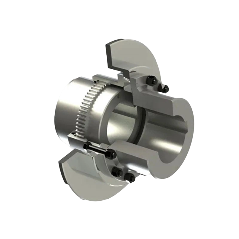
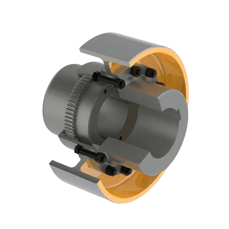
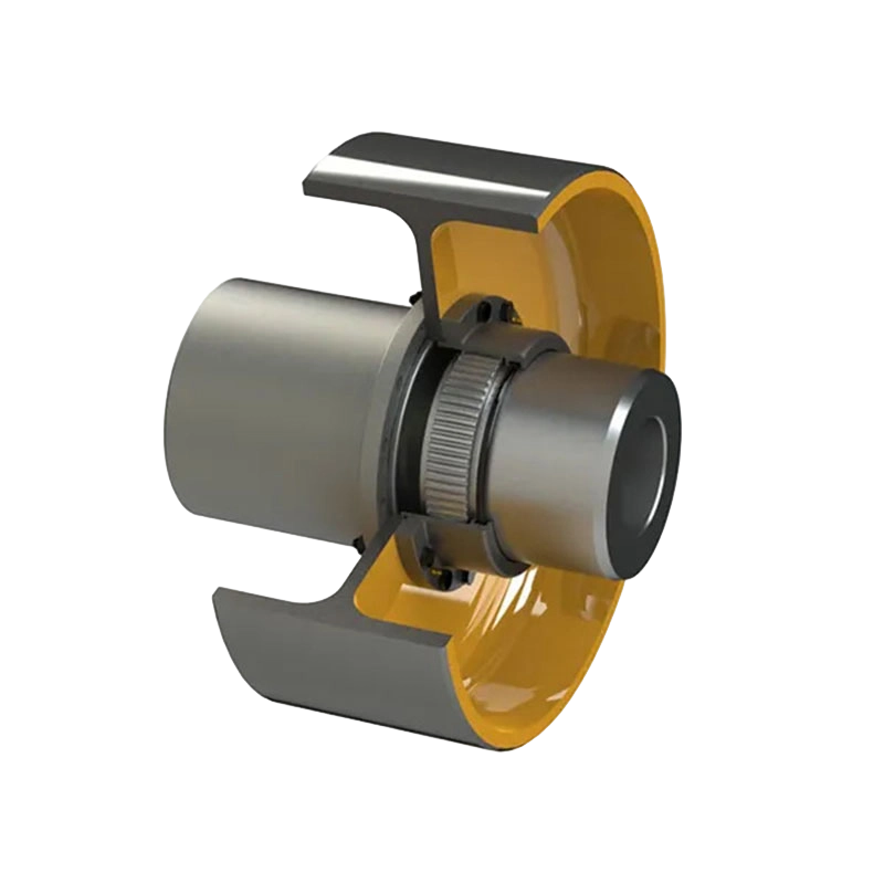
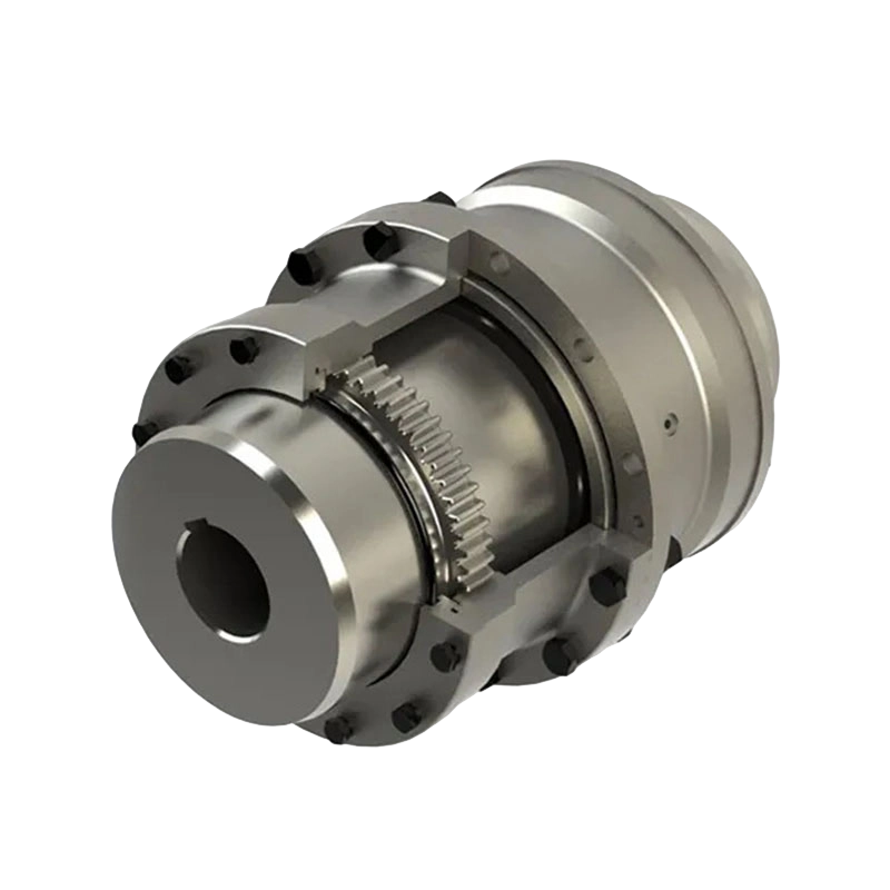
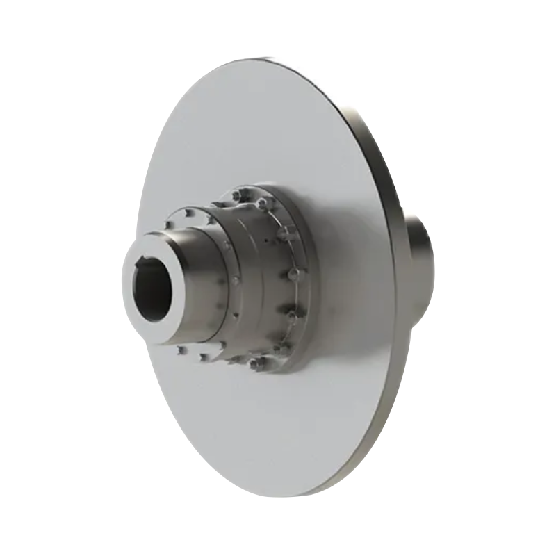
A brake drum gear coupling delivers dual-function reliability in heavy-duty power transmission because it does two structurally distinct jobs at once: it transfers rotational torque between two shafts through meshing gear teeth, and it provides an integrated drum surface that a brake shoe or band can clamp against to slow or stop the driveline. Rather than mounting a separate brake drum on its own hub further down the shaft, the drum is machined directly into the coupling body, so the same rotating mass that carries torque from a motor to a gearbox, winch, or conveyor drive also serves as the braking interface. This integration removes one shaft-mounted component from the drivetrain layout, reducing the number of separate hubs, keys, and fasteners that would otherwise need independent alignment and inspection. The gear teeth themselves handle a second role beyond pure torque transfer, since the crowned or drum-shaped tooth profile allows a controlled degree of angular movement between the internal and external gear members, which is what lets the coupling absorb shaft misalignment without relying on a flexible or elastic material to do the work.
How Non-Elastic Gear Coupling Design Handles Misalignment
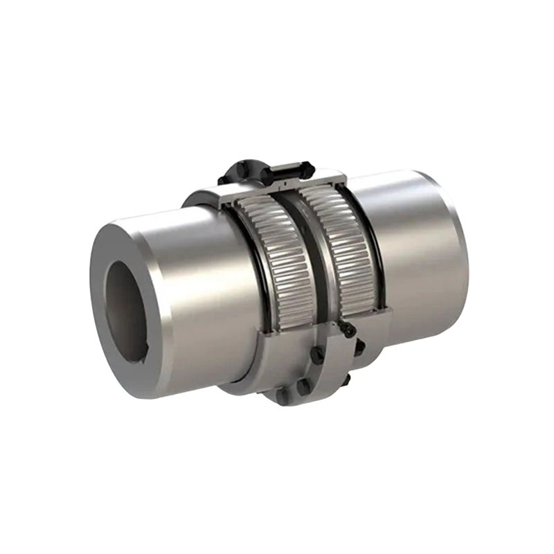
Flexible couplings that rely on non-elastic elements compensate for shaft misalignment through relative sliding movement or clearance between the mating gear teeth, rather than through the deformation of a rubber sleeve, spring pack, or elastomeric disc found in elastic coupling designs. In a gear coupling, an internally toothed sleeve engages with an externally toothed hub, and because the external teeth are machined with a slight crown or drum curvature rather than a straight profile, the mesh can accommodate angular offset between the two shafts as they rotate. This mechanism means the coupling does not depend on a wear-prone rubber component that degrades under heat, oil exposure, or ultraviolet aging, all of which are common failure points for elastomeric couplings operating in industrial plants.
Because no elastic damping material sits between the driving and driven sides, this coupling category transmits torque with comparatively high torsional stiffness, meaning very little rotational lag occurs between input and output shaft rotation. This characteristic makes non-elastic gear couplings a common choice in systems where speed needs to stay steady and load conditions remain relatively constant, such as rolling mill drives or large fixed-speed pump trains, rather than in applications with frequent torque spikes that benefit from an elastomeric buffer.
Gear Tooth Geometry and Its Effect on Load Distribution
Drum-Shaped Tooth Profile
The drum-shaped or barrel-crowned tooth form machined onto the external gear member spreads contact load more evenly across the tooth face compared to a straight-cut tooth, particularly when the coupling operates under any degree of angular misalignment. A straight tooth profile under misalignment tends to concentrate contact stress at the tooth edges, accelerating localized wear and eventually causing premature pitting or fracture at those high-stress points. The curved profile shifts this contact pattern toward the tooth center as misalignment increases, which helps preserve gear life over extended operating periods and supports the higher torque ratings this coupling category is engineered to carry.
Manufacturing Precision and Vibration Control
Dimensional accuracy during gear cutting and heat treatment directly affects how smoothly torque transfers through the mesh once the coupling is installed. Components machined with tight tolerances on tooth pitch and bore concentricity reduce the small rotational irregularities that can otherwise generate vibration at the coupling's operating speed, which matters in drivetrains connected to sensitive downstream equipment such as precision rolling stands or instrumented conveyor systems where vibration transmission affects measurement accuracy or product quality.
Materials and Surface Treatment for Corrosive or Humid Environments
Coupling bodies and gear sleeves in this category are typically forged or machined from alloy steel selected for toughness under impact loading, since the coupling frequently sits in a drivetrain position where sudden torque spikes occur during startup, jamming events, or load reversals in mining and material handling equipment. A surface coating, often a phosphate or zinc-based anti-corrosion treatment, is applied to the exterior of the coupling body and drum surface to slow oxidation in humid plant environments such as port handling equipment exposed to salt air, or paper mill drivetrains operating in consistently damp conditions. Without this treatment, surface corrosion on the drum face itself can interfere with braking friction consistency over time, making the coating a functional consideration rather than a purely cosmetic one.
Common Applications Where Combined Torque and Braking Function Matter
Drivetrains that require both continuous torque transmission and a reliable stopping mechanism at the same shaft location appear across several heavy industrial sectors. The table below outlines where this coupling type is typically applied and why the dual function matters in each setting.
| Industry | Typical Equipment | Why the Dual Function Matters |
|---|---|---|
| Steel rolling and metallurgy | Rolling mill drive shafts | Rapid stopping needed during jam or overload events |
| Mining and mineral processing | Crushers, mill drives | Torque delivery under sustained high-impact loading |
| Cranes and lifting equipment | Hoist drive drums, winches | Load holding and controlled descent braking |
| Material handling and conveying | Belt conveyor head drives | Preventing belt rollback on inclined sections |
| Fluid handling and port equipment | Pumps, compressors, port cranes | Reliable stopping in corrosive coastal environments |
Reference Technical Range for Drum Gear Coupling Series
Drum-shaped gear coupling product lines are typically manufactured across a broad range of sizes to match equipment ranging from small precision drives to ultra-heavy industrial systems. A representative specification range, based on a standardized drum gear coupling series, is outlined below.
| Parameter | Range |
|---|---|
| Nominal Torque | 0.63 kN·m to 5600 kN·m |
| Maximum Permissible Speed | Up to 6,500 r/min on smaller models |
| Bore Diameter | 16 mm to 1,040 mm |
| Bore Length | 45 mm to 900 mm |
| Unit Weight | 3.0 kg to 22.38 metric tons |
This wide sizing range allows engineers to select a coupling that matches the specific torque, speed, and shaft dimensions of a given drivetrain, rather than accepting a compromise between undersized components that wear prematurely and oversized components that add unnecessary rotating mass to the system.
Installation Considerations and Maintenance Intervals
Installing a brake drum gear coupling generally involves fewer separate parts than a shaft layout using an independent brake drum hub, since the drum surface and gear coupling body arrive as a single machined assembly rather than two components requiring separate keying and alignment checks. This simplified layout tends to shorten downtime during initial installation and during later maintenance intervals, since technicians work with one rotating assembly rather than coordinating alignment between two separately mounted hubs. Routine maintenance typically involves periodic lubrication of the gear mesh, since the sliding contact between internal and external teeth generates friction that requires grease replenishment on a scheduled basis, along with visual inspection of the drum surface for wear grooves or glazing that can develop from repeated brake shoe contact over years of service.
Why Dual-Function Design Continues to Matter in Heavy Industrial Drivetrains
As heavy machinery in steel production, mining, and material handling continues to demand higher torque capacity alongside stricter safety requirements for stopping and load holding, the appeal of combining torque transmission and braking function within a single machined component remains relevant to how engineers design compact, serviceable drivetrains. A brake drum gear coupling addresses both requirements without adding a separate shaft-mounted brake hub, offering a layout that supports the misalignment tolerance of gear coupling technology alongside the stopping function that heavy-duty rotating equipment depends on for safe operation.
- Quick Links
- About
- Products
- Our Service
- News & Events
- Contact
- Products Series
- Flexible Couplings with Non-Elastic Elements
- Flexible Couplings with Metal Elastic Elements
- Flexible Couplings with Non-Metallic Elastic Elements
- Safety Coupling
- Rigid Coupling
- Contact Us
- Tel : +86 511 8572 3800 +86 511 8572 3900
- Mobile : +86 15106109009
- Email : sales@couplingzy.com
- Add:No.1 Zhongye Yingbin Avenue, Gaozi Street, Dantu Economic Development Zone, Zhenjiang City, Jiangsu Province, China.


